Wrap Up 2017 for Hile Controls of Alabama

Process automation
The current year is closing out quickly. Here at Hile Controls of Alabama, we want to extend our thanks to all those that have supported our business and provided us with opportunities to build and improve our business and yours.

A number of product line expansions were put in place this past year.

In addition to new products, we also continued to train and learn, in order to better meet whatever challenges we face. We look forward to every opportunity to serve our customers in the new year.

Advanced Mass Flow Meter and Controller for Gases

Thermal mass flow controller for gases in laboratory or research setting
The EL-FLOW® Prestige is the latest mass flow controller
offering from Bronkhorst USA.
Image courtesy Bronkhorst USA
Bronkhorst is a globally recognized innovator in mass flow and pressure measurement and control. The company's EL-FLOW® Prestige incorporates their latest innovations in gas flow measurement and control.

The EL-FLOW® is essentially a thermal mass flow controller, and includes measurement hardware, microprocessor controller, and precision control valve in a single compact unit. Setpoint and output can be transferred to and from the unit via a PC connection, analog port, or one of several possible industrial communications protocols.

DeviceNet™, PROFIBUS DP, Modbus, PROFINET, EtherCAT® or FLOW-BUS

The instrument uses a new thermal principal for flow measurement, called Differential Temperature Balancing.  It is similar to traditional thermal mass flow measurement, but employs two heated sensors and a modified algorithm to process the comparative heat input to each. The innovation delivers a high degree of linearity, with improved stability to boost the controller accuracy.

There are several other innovations included in this latest version of the EL-FLOW® mass flow controller. More information is provided in the datasheet included below, but you are encouraged to share all your flow measurement and control challenges with process measurement and control experts. Leverage your own process knowledge and experience with their product application expertise to develop effective solutions.


Hile Controls of Alabama Expands Product Offering

oil refinery process control
Continuing its drive to provide top flight solutions to industrial process measurement and control challenges, Hile Controls of Alabama has added several new lines of instruments and equipment to its offering.


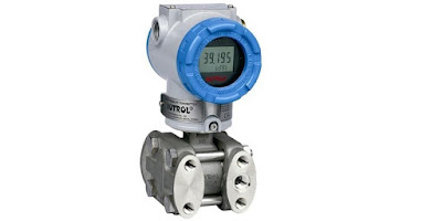
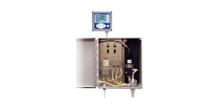
  • Tektrol provides process measurement and control products for flow, level, temperature and pressure measurement and control valves and analyzer systems.
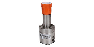
  • Premier Industries is a designer and manufacturer of proprietary specialty gas and hydraulic regulators, valves, and systems for a diverse range of applications and markets.
More will be coming to illustrate the quality products offered by these new lines for Hile. Detailed information is available through a quick contact with our office. Share your process measurement and control challenges, leveraging your own knowledge and experience with the product application expertise at Hile Controls of Alabama to develop the best solution.

Comparison of 900 MHz vs 2.4 GHz for Industrial Wireless Connectivity

depiction of wireless process signal transmission in industrial setting
IOSelect provides equipment to establish wireless
process signal connections.
Image courtesy IOSelect
Wireless transmission of measurement and control signals are the future, and present, of process control. WiFi is already prevalent in higher density environments and providing benefits of reduced cabling and more. Wireless communications also can be used to connect devices over substantial distances, even globally. This article will focus on applications of moderate to long distance that will employ point to point communications of dedicated devices.

In establishing a wireless process signal connection between two points, an initial consideration will be whether to employ 900 MHz or 2.4 GHz as the radio band. There are some general implications associated with the selection.
  • Signal attenuation over any distance is greater for 2.4 GHz than 900 MHz. This generally means that 900 MHz can cover a greater distance and provide a signal of sufficient strength to properly communicate.
  • Atmospheric attenuation for either frequency band is about the same, with a very slight advantage to 900 MHz.
  • Both frequencies require "line-of-sight" to provide predictable and reliable operation. Obstructions within that zone can degrade the signal. Any obstructions with dimensions approximating the wavelength of the signal tend to have a greater impact. The wavelength of a 2.4 GHz signal is 12.5 cm (4.52 inches), 900 MHz is 33.3 cm (84.6 inches). 2.4 GHz signals are susceptible to interference by smaller objects in the transmission path than are 900 MHz signals.
  • Without getting too technical, the height of a 900 MHz antenna will need more elevation than that of a 2.4 GHz antenna in order to provide what is known as "free space propagation". This is related to the Fresnel Zone and has greater impact as transmission distance increases.
  • FCC rules allow larger transmit power ratings for 2.4 GHz radio signals than 900 MHz, increasing the potential range for 2.4 GHz.
Having a general understanding of the factors that vary between 900 MHz and 2.4 GHz and how they might impact your installation can lead to a better project outcome. Evaluate your potential installations with the above points in mind. Their impact on any particular application can vary depending upon the distance, topography, and potential obstructions. Share your wireless communications challenges with application specialists. Combining your site and process knowledge with their product application expertise will produce an effective solution.


Wireless Transmission of Industrial Process Control Signals - Practical Considerations

industrial wireless transmitter or receiver for process measurement and control
Establishing wireless process signal connections
requires consideration of a different set of factors
than a wired installation.
Image courtesy IOSelect
Establishing wireless connections for the transmission of process measurement signals is generally a straight forward task. There are, however, a vastly different set of considerations than those for a wired transmission of the same signal. In order to select the right equipment for the job, some general comprehension of radio signals can be useful.

Radio wave frequencies are below the infrared range on the electromagnetic spectrum, thus their wavelengths are comparatively long. Three things can happen to electromagnetic radiation (radio waves) when encountering a barrier.
  • Reflectance: The wave bounces off the barrier.
  • Transmittance: The wave passes through the barrier.
  • Absorbance: The wave is stopped.
Which of the three possibilities will occur depends upon a number of factors relating to the signal and the barrier, some of which include:
  • The wavelength of the radiation
  • The intensity of the radiation hitting the barrier
  • The chemical composition of the barrier
  • The physical microstructure of the barrier
  • The thickness of the barrier
Here is a conglomeration of knowledge items pulled together from a number of public sources that can be applied when considering a wireless installation.

Milliwatts (mW) are the common measurement unit of radio frequency (RF) power. A logarithmic scale of decibels, referencing 1 mW as the zero point, provides a useful way to express the comparative strength of RF signals. Using decibels, a signal strength of 1 mW is registered as 0 dBm. RF power attenuates according to a logarithmic function, so the dBm method of expressing RF power enjoys widespread use.

Industrial wireless communications applications in North America predominantly operate in either the 2.4 GHz or 900 MHz frequency range. Higher frequency will provide more bandwidth, but at the cost of reduced transmission distance and obstacle penetration. Lower frequency can require a larger antenna to attain the same signal gain.

Transmission power is not the only solution for delivering a signal. Low power signals can be successfully received by sensitive radio equipment. Reducing the data transmission rate can increase the functional sensitivity of the receiving equipment, too.

Be mindful of the existence or potential for RF background noise in your communications environment. A higher level of background noise can hamper the effectiveness of your equipment. The "noise floor" varies throughout the frequency spectrum and is generally below the sensitivity level of most equipment. Industrial environments can sometimes provide unusual conditions which may warrant a site survey to determine the actual noise floor throughout the communications area.

Radio transmission is susceptible to environmental elements on a variable basis. Since the environment can change without notice, it is useful to know the fade margin of a wireless installation. Fade margin expresses the difference between the current signal strength and the level at which the installation no longer provides adequate performance. One recommendation is to configure the installation to provide a minimum of 10dB of fade margin in good weather conditions. This level can provide sufficient excess signal strength to overcome the diminishing effects of most weather, solar, and interference conditions.

There are a number of simple methods to determine whether an installation has at least a 10 dB fade margin. Temporarily installing a 10dB attenuator on the system antenna, or installing a length of antenna cable that yields 10dB of attenuation will allow you to determine if the installation can accommodate 10dB of environmental impact on the signal. If the system operates suitably with the attenuation installed, you have at least that much fade margin.

RF signals attenuate with the square of the distance traveled, so if transmission distance is to be doubled, then the signal power must increase fourfold.

True “line of sight” signal paths are found in a limited number of installations. The number, type, and location of obstacles in the signal path can have a significant impact on the signal and contribute to what is referred to as path loss. Probably the simplest way to reduce the impact of obstacles is to elevate the antennas above them. Obstacles, in almost every case, are affixed to the earth, so their interference is reduced by elevating antennas to “see” over the obstacles.

When the signal path extends through an outdoor area, weather conditions have an impact on the path loss, with higher moisture levels increasing the loss. Large plants, most notably heavily wooded areas, can impose substantial reduction on RF signals and may require elevating antennas above the trees or using repeaters to route the signal around a forested area.

Industrial installations routinely present many reflective obstacles in the signal path. The transmitted signal may reflect off several obstacles and still reach the receiving antenna. The received signal strength will be the vector sum of all the paths reaching the antenna. The phase of each signal reaching the antenna can impact the total signal strength in a positive or negative way. Sometimes relocating the antenna by even a small amount can significantly change the strength of the received signal.

Antenna cable contributes to signal attenuation. Use high quality cable of the shortest length possible to minimize the impact on performance.

Share your connectivity challenges with application specialists, leveraging your own knowledge and experience with their product application expertise to develop an effective solution.

Programmable Automation Controller Flexes into Many Applications

programmable automation controller modular backplane
One of several programmable automation controller
backplane configurations for the T2750.
Image courtesy Eurotherm
The Eurotherm T2750 is a high performance modular control unit that provides redundancy and capability that are unmatched in a consolidated single unit. The controller backplane, of which there are several variants to accommodate the scope of I/O needed for a wide range of process applications, can be populated from an array of I/O and function modules providing a customized setup that closely matches project requirements.

Capabilities of the programmable automation controller include:
  • I/O Block
  • Communications
  • Signal Conditioning
  • Control
  • Timing
  • Logic
  • Math
  • Valve and Motor Control
  • Diagnostics
  • Recorder
  • More
There is much more to learn about the highly capable T2750 Programmable Automation Controller. For more information, share your process automation and control challenges with a product application specialist, leveraging your own process knowledge and experience with their product application expertise to develop an effective solution.


Pneumatic Volume Booster

pneumatic control system volume booster
Pneumatic control system volume booster replicates a control
signal with higher available air flow at the output.
Image courtesy ControlAir, Inc.
A volume booster is employed in a pneumatic control system to reproduce a low flow control signal with a higher regulated flow output pressure. It uses an unregulated input pressure to maintain a regulated output pressure under flowing and non-flowing conditions. Many applications exist, a common one being a valve actuator which may require a substantially larger air flow rate than can be delivered by the control signal. The volume booster will reproduce the pressure of the input signal at its output, but with a larger available flow rate available from an independent source.

The volume booster is connected to the air supply line, with the output routed to whatever device is to be controlled. The control signal to the volume booster originates at another device, such as a transducer, valve positioner or other control means.

This pneumatic input signal serves as the output pressure setpoint for the booster. The volume booster regulates the flow from the supply line to deliver the sepoint outlet pressure, while allowing the booster to flow the maximum volume of the supply line. Boosters may also be referred to as pilot-operated regulators, as your control or pilot signal maintains the outlet pressure control.

The regulated output of a pneumatic volume booster can be any of several options to match the driven device requirements.
  • A direct reproduction of the pneumatic control signal
  • A multiple of the pneumatic control signal 
  • A fraction of the pneumatic control signal
The volume booster ratio is the multiplier or divider of signal pressure to output pressure. For example, a 2:1 ratio means output pressure is 1/2 the signal pressure. Similarly, a 1:2 ratio would provide output pressure twice the signal pressure. The actual output pressure, regardless of the ratio, is limited by the supply pressure.

There is substantial flexibility in the configuration and variants of volume boosters, enabling selection of the right unit for every application. Share your pneumatic control system challenges with process automation specialists, leveraging your own knowledge and experience with their product application expertise to develop effective solutions.


New Product - Pressure Regulator For Very Low Flow Applications

low flow high pressure regulator valve
The JRDL Series pressure regulator for very low flow applications.
Image courtesy LowFlow - Division of Jordan Valve
Jordan Valve, under their Low Flow brand name, released a new series of products to expand their already extensive J-Series line of pressure regulators and back pressure regulators.

The JRDL Series is a diaphragm operated pressure regulator intended for use in applications requiring very low flow rates.  Line sizes include 1/2", 3/4", and 1" (along with metric equivalents) with threaded, socket weld, or flange connections. The standard outlet pressure ranges extend up to 400 PSI, with custom configurations available. A host of possible configurations, seal materials, and options round out the offering.

More technical detail and illustration is provided in the datasheet included below. Share your fluid control challenges with valve specialists, leveraging your own process knowledge and experience with their product application expertise to develop effective solutions.


Total Chlorine Analyzer for Water or Seawater Applications

total chlorine analyzer for water or seawater with cabinet open
Total chlorine analyzer for water and seawater application.
Image courtesy Emerson - Rosemount
Chlorine has many uses throughout commercial, municipal, and industrial processes. Managing chlorine levels is an important part of many process control applications. The measurement of total chlorine in a water or seawater sample is accomplished with the Rosemount TCL Total Chlorine System.

The cabinetized unit includes a sampling system, total chlorine sensor, and transmitter to deliver total chlorine measurement to a control and monitoring system. The cabinet is fabricated from fiber reinforced plastic, making it suitable for marine environments. The transmitter provides analog outputs for temperature and chlorine, with a range of industrial communications options available.

The unit contains enough reagent to last approximately two months. Acetic acid and potassium iodide are injected into the sample. The resulting depression in the sample pH allows total chlorine to react with the potassium iodide to form iodine. The sensor measures concentration of iodine, and the transmitter interprets and displays the level of total chlorine from that measurement. The transmitter also serves as the operator interface for diagnostics, calibration, and setup. Sensor maintenance is fast and easy. Replacing the membrane requires no special tools or fixtures. Simply place the membrane assembly on the cathode and screw the retainer in place. Installing a new membrane and replenishing the electrolyte takes only a few minutes.

More detail is provided in the datasheet included below. Share all your fluid analytic challenges with process measurement specialists. Leverage your own process knowledge and experience with their product application expertise to develop effective solutions.


Valves, Regulators, Steam Traps, and More for Sanitary Processing


Steriflow manufactures a broad range of fluid control and regulator products for use in sanitary operations, such as in the pharmaceutical, food, beverage, and cosmetic industries. The video provides a comprehensive overview of the various products available from Steriflow.

Share all your sanitary process fluid control requirements with process measurement and control specialists, leveraging your own knowledge and experience with their product application expertise for develop effective solutions.

Magnetic Flow Meters: Principles and Applications

industrial flow meters
Industrial flowmeters
Image courtesy Flow Technology, Inc.
Crucial aspects of process control include the ability to accurately determine qualities and quantities of materials. In terms of appraising and working with fluids (such as liquids, steam, and gases) the flow meter is a staple tool, with the simple goal of expressing the delivery of a subject fluid in a quantified manner. Measurement of media flow velocity can be used, along with other conditions, to determine volumetric or mass flow. The magnetic flow meter, also called a magmeter, is one of several technologies used to measure fluid flow.

In general, magnetic flow meters are sturdy, reliable devices able to withstand hazardous environments while returning precise measurements to operators of a wide variety of processes. The magnetic flow meter has no moving parts. The operational principle of the device is powered by Faraday’s Law, a fundamental scientific understanding which states that a voltage will be induced across any conductor moving at a right angle through a magnetic field, with the voltage being proportional to the velocity of the conductor. The principle allows for an inherently hard-to-measure quality of a substance to be expressed via the magmeter. In a magmeter application, the meter produces the magnetic field referred to in Faraday’s Law. The conductor is the fluid. The actual measurement of a magnetic flow meter is the induced voltage corresponding to fluid velocity. This can be used to determine volumetric flow and mass flow when combined with other measurements.

The magnetic flow meter technology is not impacted by temperature, pressure, or density of the subject fluid. It is however, necessary to fill the entire cross section of the pipe in order to derive useful volumetric flow measurements. Faraday’s Law relies on conductivity, so the fluid being measured has to be electrically conductive. Many hydrocarbons are not sufficiently conductive for a flow measurement using this method, nor are gases.

Magmeters apply Faraday’s law by using two charged magnetic coils; fluid passes through the magnetic field produced by the coils. A precise measurement of the voltage generated in the fluid will be proportional to fluid velocity. The relationship between voltage and flow is theoretically a linear expression, yet some outside factors may present barriers and complications in the interaction of the instrument with the subject fluid. These complications include a higher amount of voltage in the liquid being processed, and coupling issues between the signal circuit, power source, and/or connective leads of both an inductive and capacitive nature.

In addition to salient factors such as price, accuracy, ease of use, and the size-scale of the flow meter in relation to the fluid system, there are multiple reasons why magmeters are the unit of choice for certain applications. They are resistant to corrosion, and can provide accurate measurement of dirty fluids – making them suitable for wastewater measurement. As mentioned, there are no moving parts in a magmeter, keeping maintenance to a minimum. Power requirements are also low. Instruments are available in a wide range of configurations, sizes, and construction materials to accommodate various process installation requirements.

As with all process measurement instruments, proper selection, configuration, and installation are the real keys to a successful project. Share your flow measurement challenges of all types with a process measurement specialist, combining your process knowledge with their product application expertise to develop an effective solution.


Dampers and Louvers Used in Power Plants, Refineries, Boilers, and Furnaces

pneumatic damper drives, damper positioners
Several sizes of pneumatic damper drives
Image courtesy Rosemount Analytical - Emerson
A damper (also known as a louver) is a multi-element flow control device generally used to throttle large flows of air at low pressure. Dampers find common application in furnace and boiler draft control, and in HVAC systems. Common damper designs include parallel and radial configurations of the vanes.

Parallel-vane dampers resemble a Venetian blind, with multiple parallel rectangular vanes synchronously rotated to throttle flow through a rectangular opening. The rectangular shape of the assembly facilitates installation in rectangular duct. The vanes are mechanically linked so they function as one. A manual drive can be used to set the vane position. More commonly, an automated drive positions the vanes in response to a control signal.

Radial-vane dampers use multiple vanes arranged like petals of a flower to throttle flow through a circular opening or duct. Levers and linkages on the periphery of the tube synchronize the motion of the multiple vanes so they rotate at the same angle. Mechanical linkage to an external drive point enables position control similar to that of rectangular dampers.

Automated dampers can be positioned by a number of actuation means. A common design employs a double action pneumatic cylinder, along with integrated pilot valve and controls, to position the damper vanes. A example of such a device is pictured above and detailed in the document provided below.

Used in critical applications commonly found in power plants, refineries, boilers, and furnaces, these damper and drive combinations are coupled with combustion analysis instruments to provide precise combustion gas management and increased boiler efficiency,  with lower fuel consumption, reduced emissions, and reduce maintenance cost.

Share your combustion control and large air flow control challenges with an application specialist. Leverage your own knowledge and experience with their product application expertise to develop an effective solution.

Parts of this post are reprinted from Lessons In Industrial Instrumentation by Tony R. Kuphaldt – under the terms and conditions of the Creative Commons Attribution 4.0 International Public License.


High Accuracy Low Differential Pressure Gauge


Dwyer has a new line of their well recognized Magnehelic differential pressure gauges. The new high accuracy series is intended for applications where accuracy in low pressure or differential pressure ranges is key. Six point calibration certificate, mirrored scale, wide selection of ranges, and the ability to customize the instrument are a few of the key new features. The short video tells the story.

Reach out to a process instrumentation specialist for all the details on the new models. Share your process measurement challenges with them, combining your own knowledge and experience with their product application expertise to develop an effective solution.

Manufacturer Donates Exhibit to Science Museum

equipment or control enclosure cooling units of various sizes
Advanced Cooling Technologies manufactures a range of  heat
transfer products, such as these enclosure coolers.
Image courtesy of Advanced Cooling Technologies
When a business does a good public service deed, it should be known publicly. One of the manufacturers represented by Hile Controls of Alabama, Advanced Cooling Technologies, created and donated an interactive science exhibit on heat transfer principles to the Lancaster Science Factory in Lancaster, PA.

You can read more about the exhibit and the Lancaster Science Factory in the article included below. Kudos and applause to ACT for taking the time and effort to create and contribute this exhibit that helps students learn about science.

For more information about ACT products, you can contact Hile Controls of Alabama.


In Situ Oxygen Analyzer


Watch this video from Rosemount Analytical. A product manager outlines the operation and application of the model 6888 in situ oxygen analyzer. Share your process analytical challenges with the process measurement and control specialists at Hile Controls of Alabama for practical and effective solutions. The combination of your process knowledge and experience with the input of a product application specialist will yield effective solutions.

Controlling Steam Heat Trace Lines

steam tracing temperature regulator valve
Specialty control valve regulates temperature
in steam heat tracing lines.
Image courtesy Jordan Valve
Steam is a commonly employed heat source for freeze protection or other heat tracing of process lines. Other than being an efficient heat transfer medium, steam provides the advantage of not being a possible source of ignition, extremely useful in areas where the presence of flammable vapors is a possibility.

Regardless of the method used to deliver heat, all heat trace operations consume energy. Control of the heat trace operation not only saves cost through energy conservation, but prevents potential deterioration, through overheating, of materials that may be in proximity to the heated line.

When steam is used, a well designed temperature regulator can provide control of steam flow through the heating system. Specially adapted for heat tracing operations, the Jordan Valve Mark 86 senses ambient temperature and adjusts steam flow as the ambient temperature changes. The completely self-contained unit includes temperature sensing element, diaphragm, and a sliding gate valve to regulate steam flow.

More detail is provided in the document included below. Share all your fluid flow control challenges and requirements with a flow control specialist, combining your own knowledge and experience with their product application expertise to develop an effective solution.


Industrial Wireless is a Mainstream Connection Method For Process Measurement

industrial wireless transmitter or receiver
Industrial wireless transmitters and receivers are
compact and easy to apply
Image courtesy of IOSelect
Wireless connections to process instrumentation have evolved to a point where they are uncomplicated and inexpensive to implement. Many facilities rely on wireless connections, either via a network (wifi) or point to point communications. The benefits of wireless are well known to those already among users of the technology.
  • Safety: Wireless connections can reduce personnel exposure to hazardous environments or situations that previously required human intervention or a manual gauge or instrument reading.
  • Easy Scale-up: Adding points on a network is generally a simple incremental process.
  • Operational Advantage: When deployed to replace manual instrument or gauge readings, real time data for diagnostics and efficiency measurements are now available. Information that is more accurate, timely, and consistent will produce better results.
  • Installation Savings: Installation of wireless connected assets has been reported to be up to 10 times less expensive than wired installation. The reduced space and planning for cables and conduit can make what were once complex and time consuming operations much quicker and easier.
  • Mobility: Wireless technology allows for real time connections to mobile platforms. Whether within a plant, on the road, or on the high seas, there are wireless products that can make the connection.
  • Distance: Don't just think WiFi, think radio, think satellite, think cellular. Connections can be established across very long distances using standard products from the industry.
  • Conversion of Legacy Devices: Many existing in-place devices can have their wired connections replaced with a wireless version. This accommodates a staged transition from wired to wireless in facility.
The transmission is accomplished in either the 900 MHz or 2.4 GHz band, delivering adequate range and power for most facility-wide applications. Obstructions can be overcome with the use of a strategically located repeater. Properly planned and configured, there are few limits to the distance a wireless connection can span.
Point to point wireless connections between, for example, a temperature transmitter and a recorder are easy to create. Most process sensors have very small power requirements, as do the wireless transmission and reception units. Power, if line voltage is not available at the location, can be provided by batteries, or combination of battery and photovoltaic. The 4-20 mA signal from the temperature transmitter serves as the input signal to the wireless transmitter. The analog signal is converted to a digital value and encrypted prior to transmission. A receiver at the recorder decrypts the digital signal and converts it back to a 4-20 mA analog output that serves as the input signal to the recorder. Wireless transmitter and receiver must be set to the same channel, but otherwise, the equipment handles all the work. If you can find your way around a smart phone, you can make a wireless point to point process connection.

There are likely many applications going unfulfilled because the cost or feasibility of making a wired connection is holding the project back. Reconsider the project using industrial wireless technology and you may find that the project becomes an attractive prospect.

Share your connectivity challenges with the experts at Hile Controls of Alabama, combining your own process knowledge and experience with their wireless communications expertise to develop an effective solution.
Basic Checklist for Accurate pH/ORP Measurements

process measurement sensors for pH and ORP
Sensors for pH/ORP measurement
Courtesy Emerson - Rosemount Analytical
The measurement of pH/ORP is a common practice among processors of water. Though the task is ubiquitous, it still remains an analytical process that requires careful execution in order to achieve reliable results.

Emerson contributed an article to wateronline.com, a journal focused on the many aspects and uses of water across all sectors. The article (which can be found here at the publication site) summarizes the basics one needs to approach pH/ORP measurement. All credit for the article goes to the authors at Emerson, and it is shared here to assist our readers in solidifying their skill, accuracy, and understanding of this important measurement.

Share your process measurement challenges of all types with instrumentation specialists, combining your own knowledge and experience with their product application expertise to develop effective solutions.


Foundation Fieldbus – Part Two

storage tanks
Almost any operation can benefit from incorporating
Foundation fieldbus
Since automatic control decisions in FOUNDATION fieldbus are implemented and executed at the field instrument level, the reliance on digital signals (as opposed to analog) allows for a streamlined configuration of direct control system ports. If the central control device were to become overloaded for any reason, tasks related to control decisions could still be implemented by operators in the field. This decentralization of the system places less burden and emphasis on the overall central control unit, to the point where, theoretically, the central control unit could stop functioning and the instrumentation would continue performing process tasks thanks to the increased autonomy. Allowing for the instrumentation to function at such an increased level of operation provides a proverbial safety net for any system related issues, with the capacity for independent functionality serving as both a precaution and an example for how process technology continues to evolve from analog solutions to fully end to end digital instrumentation.

Even in terms of the FOUNDATION compliant instrumentation itself, there were two levels of networks being developed at this increased level of operation, initially: the first, H1, was considered low speed, while H2 was considered high speed. As the design process unfolded, existing Ethernet technology was discovered to fulfill the needs of the high speed framework, meaning the H2 development was stopped since the existing technology would allow for the H1 network to perform to the desired standards. The physical layer of the H1 constitutes, typically, a two-wire twisted pair ungrounded network cable, a 100 ohm (typical) characteristic impedance, DC power being conveyed over the same two wires as digital data, at least a 31.25 kbps data rate, differential voltage signaling with a defined threshold for both maximum and minimum peak receive rates, and Manchester encoding. Optical fiber can be used on some installations in lieu of the twisted pair cable.

Most of these specifications were exactly designed to withstand extremely challenging process control environments while still not abandoning the philosophy of being easy to build and implement, especially in terms of new system establishment. The most crucial aspects of many process control systems are streamlined together, allowing for consistent communication and synchronization. All aspects are viewable from both the legacy central controller and also via each individual device. Despite the data rate of 31.25 kbps being relatively slow, what is sacrificed in terms of speed is more than made up for in terms of the system being compatible with imperfect cables and other hiccups which may destabilize a network with faster speeds. The evolved technology, ease of installation, and durability have made the H1 network a widely used implementation of the FOUNDATION fieldbus technology. The standard is currently considered one of a few widely adopted industrial process control communications protocols.

Foundation Fieldbus Equipped Instrumentation – Part One

Foundation filedbus capable pressure transmitter
Foundation fieldbus capable instruments and devices
provide benefits to process operators
Image courtesy Autrol
Autonomous control and digital instrumentation are two capabilities enabling highly precise or complex execution of process control functions. FOUNDATION fieldbus instrumentation elevates the level of control afforded to digital field instrumentation where, instead of only communicating with each other, instruments involved in particular process control systems can independently facilitate algorithms typically reserved for instruments solely dedicated to controlling other instruments. Fieldbus capable instrumentation has become the standard instrumentation for many process industry installations due to the fact the FOUNDATION design principle streamlines process systems. A large contributor to FOUNDATION’s success has been faster installation as opposed to operational controllers which do not feature the fieldbus configuration. Newer process companies, or process control professionals seeking to establish a new system, have gravitated towards fieldbus due to the combined advantages of system conciseness and ease of implementation.

In a typical digital control system, dedicated controllers communicate with field instrumentation (the HART protocol is a prime example of digital communication at work in the industry). The host system controls configuration of instruments and serves as a central hub where all relevant control decisions are made from a single dedicated controller. Typically, these networks connect controllers and field devices through coupling devices and other ‘buses’ which streamline many different instruments into a complete system.

FOUNDATION fieldbus approaches the same network scheme with an important difference. Whereas in a legacy or more conventional system, either algorithmic or manual decisions would need to be implemented via the dedicated system level controllers, instruments utilizing FOUNDATION fieldbus architecture can execute control algorithms at the local device level. The dedicated controller hub is still present, so that operators can view and monitor the entire network concurrently and make status changes. Algorithmic execution of control functions becomes entirely device reliant thanks to the FOUNDATION protocol. Additionally, even though FOUNDATION implements an advanced configuration, some operators use the capabilities introduced in the fieldbus upgrade to implement specific algorithms via each device while concurrently maintaining algorithms in the central controller. This dual algorithmic configuration allows for several advantages, including the ability for increased system precision.

Since individual devices in the control process are calibrated and able to execute their own control functions, issues in the process with particular devices can be isolated and dealt with in a more specified manner by technicians using the instruments in the field. The central operator retains the capacity to use the control hub to alter and direct the control system.

In Situ Gas Measurement Instrument for Emission Monitoring and Combustion Control

in situ gas monitor
Model GM 35 in situ gas monitor
Image courtesy of Sick USA
The measurement of gas component concentration, especially in operations involving combustion, is necessary to assure regulatory compliance, as well as levels of fuel consumption efficiency. Measurement instrumentation that is reliable, easy to maintain, and accurate delivers needed information without a substantial burden.

What are some attributes of a gas measurement instrument that may prove useful for industrial installations?

  • Ability to measure multiple constituents, such as CO, CO2, H2O, or N2O with a single instrument. 
  • Built-in capability for zero and span test without the need for test gases.
  • In place continuous operation with real time measurement output, eliminating the need for gas sampling or transport. Measurement is accomplished in the process flow.
  • Measurement of temperature and pressure included in unit function.
  • Model available in cross duct and single ended probe type versions.
  • Rugged, properly rated, enclosures for installation outdoors in challenging industrial environments
Each installation scenario will have its own challenges, and each process its own set of measurement requirements. Share your application specifics with a process measurement specialist, combining your own knowledge and experience with their instrument application expertise to develop an effective solution.


Power System Surge Protection Device


Investments of time and financial resources to operate any business process can have their yield crushed in the blink of an eye by power system anomalies. Businesses and processes run on electric power. Greater levels of IT complexity, process instrumentation, or other electrical equipment generally bring higher levels of exposure to power line surges that can bring unexpected downtime or equipment damage to a going concern.

Prevention through protection is the only available course of action for hardening facilities to the potentially damaging effects of line surges. Dehn, Inc. manufactures products that provide solutions for lightning and surge related problems. Surge protectors and lightning current arrestors, available as compact DIN rail mounted units, function as protective devices for motors, IT equipment, process controls, and instrumentation.

The video below provides a view of how the protective devices function. Without a protection plan in place, any facility is exposed to potential damage. Share your plans and challenges with a product application specialist, combining your facilities knowledge with their product application expertise to develop an effective solution.

Limiting Control Enclosure Temperature Rise

sealed enclosure cooling units heat pipe heat sink
Cooling units for enclosures utilize heat pipe technology and passive heat
sinks to limit enclosure temperature rise.
Courtesy Advanced Cooling Technologies
Control and equipment enclosures are most often tightly sealed for the safety of personnel, as well as the protection of interior components from environmental intrusion. This physical barrier also inhibits the dissipation of heat produced by devices within the enclosure. Electrical and electronic gear employed in control and measurement systems commonly has an upper limit for the temperature of its operating environment. Above that maximum, performance becomes undefined and devices may deteriorate, malfunction, or fail.

Advanced Cooling Technologies specializes in the design and manufacture of cooling devices for control and equipment enclosures. The company employs heat pipe technology, as well as heat sinks, to transfer substantial amounts of heat from within sealed enclosures. The special design of the cooling units maintains the rated performance of the enclosure and effectively moves heat from enclosure interior to surrounding environment. Units encompass a range of sizes, configurations and capacities.

Share your enclosure cooling challenges with product application specialists, combining your own knowledge and experience with their product application expertise to develop effective solutions.


Hydrostatic Pressure Measurement for Liquid Level

smart pressure transmitter for industrial process measurement and control
Smart transmitters are capable of performing advanced calculations
to infer liquid level from hydrostatic pressure measurement
Courtesy Autrol America
Pressure measurement is an inferential way to determine the height of a column of liquid in a vessel in process control. The vertical height of the fluid is directly proportional to the pressure at the bottom of the column, meaning the amount of pressure at the bottom of the column, due to gravity, relies on a constant to indicate a measurement. Regardless of whether the vessel is shaped like a funnel, a tube, a rectangle, or a concave polygon, the relationship between the height of the column and the accumulated fluid pressure is constant. Weight density depends on the liquid being measured, but the same method is used to determine the pressure.

A common method for measuring hydrostatic pressure is a simple gauge. The gauge is installed at the bottom of a vessel containing a column of liquid and returns a measurement in force per unit area units, such as PSI. Gauges can also be calibrated to return measurement in units representing the height of liquid since the linear relationship between the liquid height and the pressure. The particular density of a liquid allows for a calculation of specific gravity, which expresses how dense the liquid is when compared to water. Calculating the level or depth of a column of milk in a food and beverage industry storage vessel requires the hydrostatic pressure and the density of the milk. With these values, along with some constants, the depth of the liquid can be calculated.

The liquid depth measurement can be combined with known dimensions of the holding vessel to calculate the volume of liquid in the container. One measurement is made and combined with a host of constants to determine liquid volume. The density of the liquid must be constant in order for this method to be effective. Density variation would render the hydrostatic pressure measurement unreliable, so the method is best applied to operations where the liquid density is known and constant.

Interestingly, changes in liquid density will have no effect on measurement of liquid mass as opposed to volume as long as the area of the vessel being used to store the liquid remains constant. If a liquid inside a vessel that’s partially full were to experience a temperature increase, resulting in an expansion of volume with correspondingly lower density, the transmitter will be able to still calculate the exact mass of the liquid since the increase in the physical amount of liquid is proportional to a decrease in the liquid’s density. The intersecting relationships between the process variables in hydrostatic pressure measurement demonstrate both the flexibility of process instrumentation and how consistently reliable measurements depend on a number of process related factors.

Solutions to process instrumentation and measurement challenges are most effective when developed in concert with a product application specialist. The combination of user knowledge and experience with product application expertise will lead to a successful project.

Added Services Enhance Product Value

handshake by collaborators on industrial process control automation project
Collaboration and cooperation leverages the pool of knowledge
and experience brought to bear on problem solving
We have written previously about the contribution of a technical sales representative and the added value he or she can bring to the purchase of a physical product. With a daunting array of potential product variants available, it can be difficult and time consuming to reach a knowledge level that enables a confident selection of process automation products for a specialized application. The tech sales rep's knowledge of currently available products and their application specialties and limitations can speed the selection process and contribute to a positive outcome for for all stakeholders.

At the company level, many technical representatives commit to bringing factory level training resources to their customers. Reading instruction manuals can often fail to instill real understanding about the application, use, and upkeep of process and automation gear. Plus, manuals provide only one way communication. Training conducted by experienced, knowledgeable, factory trained individuals can instill almost tangible levels of comprehension in operators, users, and supporters of process and automation equipment.

Field services, in the form of start-up, calibration, repair, or regular maintenance of instruments and equipment are also provided by many technical sales firms. Again, bringing to bear broad experience and factory level training, technical representatives can function as an efficient outsource for essential tasks that may require special skills or knowledge. Repair, whether in-house or facilitated through the factory, is another way in which technical representatives leverage their experience and knowledge into offerings that bring value to their customer base.

Face it, if all that was needed was quick delivery of process and automation gear, Amazon.com would be your primary supplier. These are sophisticated instruments, apparatus, and equipment, requiring skill, knowledge, and experience to assure proper selection, installation and operation. A good technical rep firm knows that its customers need more than a product in a box or crate. It's results that count, output, and Hile Controls of Alabama is committed to assisting customers wherever Hile's expertise can help leverage positive outcomes for their customers.

Product Line Expands With Heat Sink and Heat Pipe Sealed Enclosure Coolers

sealed enclosure cooling products
Sealed enclosure coolers employing heat sink and heat pipe technology
Courtesy Advanced Cooling Technologies
Control and equipment enclosures provide a level of personnel safety, as well as protection of sensitive components from damage from operations, mishap, or the environment. Hile Controls of Alabama recently expanded and complemented their product offering with the sealed enclosure coolers from Advanced Cooling Technologies (ACT).

The cooling units employ heat sinks or heat pipes to transfer heat from within sealed control or equipment cabinets to the surrounding air. Cooling is accomplished while maintaining the enclosure rating for NEMA 12, 3R, 4, or 4X. The units carry necessary listings or approvals for incorporation by integrators into custom built equipment or OEM equipment.

A datasheet is provided below with more detailed information. Share your enclosure cooling requirements with product application specialists, combining your own process knowledge and experience with their product application expertise to develop an effective solution.

Hile Controls of Alabama Expands Product Offering With HART Communicator


Hile Controls of Alabama has complemented and expanded its process measurement and control offering with the ProComSol line of HART communications software.

The HART communications software from ProComSol is based on the SDC-625 software from the HART Communication Foundation. Since its release in 2007, the software has developed into a full featured, stable, and reliable platform through the open source development process. Years of in-field use and user feedback are incorporated into the current version that provides full configuration saving and download. The video provides an overview of the ease of use and functionality of the package for any facility utilizing HART enabled devices.

More information is available from process control experts. Share your process measurement and control challenges. Combine your own knowledge and experience with the product application expertise of a specialist to develop effective solutions.

Water Quality Analysis – Constituent Survey Part 3

water with bubbles
Water contains more than H2O
What we know as “water” can consist of many non-H2O components in addition to pure water. This three part series has touched on some of the constituents of water that are of interest to various industrial processors. The first installment reviewed dissolved oxygen and chloride. The second article covered sulfates, sodium, and ammonia.

To conclude the three part series on water quality analysis in process control related industrial applications we examine silica, another element which in sufficient quantities can become a confounding variable in water for industrial use. In natural settings, silica, or silicon dioxide, is a plentiful compound. Its presence in water provides a basis for some corrosion-inhibiting products, as well as conditioners and detergents. Problems arise, however, when high concentrates of silica complicate industrial processes which are not designed to accommodate elevated levels. Specifically, silica is capable of disrupting processes related to boilers and turbines. In environments involving high temperature, elevated pressure, or both, silica can form crystalline deposits on machinery surfaces. This inhibits the operation of turbines and also interferes with heat transfer. These deposits can result in many complications, ranging through process disruption, decreased efficiency, and resources being expended for repairs.

The silica content in water used in potentially affected processes needs to be sufficiently low in order to maintain rated function and performance. Silica analyzers provide continuous measurement and monitoring of silica levels. The analyzers detect and allow mitigation of silica in the initial stages of raw material acquisition or introduction to prevent undue disruption of the process. Additionally, a technique called power steam quality monitoring allows for the aforementioned turbine-specific inhibition – related to silica conglomerates reducing efficacy and physical movement – to be curtailed without much issue. The feedwater filtration couples with a low maintenance requirement, resulting in reduced downtime of analytic sequences and a bit of increased peace of mind for the technical operator.

While silica and the other compounds mentioned in this series are naturally occurring, the support systems in place to expertly control the quality of water is the most basic requirement for harvesting one of the earth’s most precious resources for use. As a matter of fact, the identification and control of compounds in water – both entering the industrial process and exiting the industrial process – demonstrates key tenets of process control fundamentals: precision, accuracy, durability, and technological excellence paired with ingenuity to create the best outcome not just one time, but each time. 

Share your water quality analysis challenges with process analytics specialists, combining your own unique knowledge and experience with their product application expertise to develop effective solutions.

Water Quality Analysis – Constituent Survey (Part 2)

aerial view of sewage water treatment plant
Sewage treatment is but one area where
water quality measurements are important
It would be difficult to understate the role and importance of water in industrial processing, even our own biological existence. In the first installment of this series, the roles of dissolved oxygen and chlorides were covered. 

Continuing the examination of water quality monitoring in municipal and industrial processes, another key variable which requires monitoring for industrial water use is sulfate. Sulfate is a combination of sulfur and oxygen, salts of sulfuric acid. Similarly to chlorides, they can impact water utilization processes due to their capability for corrosion. The power generation industry is particularly attuned to the role of sulfates in their steam cycle, as should be any boiler operator. Minerals can concentrate in steam drums and accelerate corrosion. Thanks to advancements in monitoring technology, instruments are available which monitor for both chlorides (covered in the previous installment in this series) and sulfates with minimal supervision needed by the operator, ensuring accurate detection of constituent levels outside of an acceptable range. Ionic separation technologies precisely appraise the amount of sulfate ions in the stream, allowing for continuous evaluation and for corrective action to be taken early-on, avoiding expensive repairs and downtime. 

Another substance worthy of measurement and monitoring in process water is sodium. Pure water production equipment, specifically cation exchange units, can be performance monitored with an online sodium analyzer. Output from the cation bed containing sodium, an indication of deteriorating performance, can be diverted and the bed regenerated. Steam production and power generation operations also benefit from sodium monitoring in an effort to combat corrosion in turbines, steam tubes, and other components. Sodium analyzers are very sensitive, able to detect trace levels. 

Ammonia is comprised of nitrogen and hydrogen and, while colorless, carries a distinct odor. Industries such as agriculture utilize ammonia for fertilizing purposes, and many other specializations, including food processing, chemical synthesis, and metal finishing, utilize ammonia for their procedural and product-oriented needs. An essential understanding of ammonia, however, includes the fact that the chemical is deadly to many forms of aquatic life. Removing ammonia from industrial wastewater is a processing burden of many industries due to the environmental toxicity. 

Methods for removing ammonia from wastewater include a biological treatment method called ‘conventional activated sludge’, aeration, sequencing batch reactor, and ion exchange. Several methods exist for in-line or sample based measurement of ammonia concentration in water. Each has particular procedures, dependencies, and limitations which must be considered for each application in order to put the most useful measurement method into operation. 

As water is an essential part of almost every facet of human endeavor and the environment in which we all dwell, the study and application of related analytics is an important component of many water based processes. The variety of compounds which can be considered contaminants or harmful elements when dissolved or contained in water presents multiple challenges for engineers and process operators. Share your water quality analysis and monitoring challenges with a process measurement expert, combining your own knowledge and experience with their product application expertise to develop effective solutions.