Showing posts with label flow meter. Show all posts

Precise and Robust Gas Flow Meter for Flare Gas or Flare Stack Applications

FLOWSIC100 Flare-XT

Flare stacks are found on nearly every oil and gas installation as part of the waste gas system and as a controlled vent for high volumes of combustible gases during an upset. The pressure, volume flow, and gas composition in a flare stack can vary significantly over short periods due to their nature. Ultrasonic flow meters are well suited for reliable process control of flares due to their accurate measurement. Flow rates range from almost zero to more than 120 m/s, ensuring the optimum ratio of O2 and steam to combustion gas is maintained and that the actual volume of flared gas is determined. 

Sick's FLOWSIC100 Flare-XT ultrasonic gas flow measuring instrument for flare gas measurement or flare metering is a perfect solution. The high-resolution measurement sensor and innovative design specifically for the applications in petroleum refineries, natural gas processing, and offshore and onshore oil and gas plants. Applications for the FLOWSIC100 Flare-XT include emission control or monitoring, detection of flare gas leaks, steam flow measurement, gas loss monitoring, steam injection in flare gas burning, process optimization, and condition monitoring. Gas velocity, temperature, volume and mass, mass flow rate, molecular weight, volumetric flow a. c., volumetric flow s. c., and sound velocity are all measured by the gas flow meter. The flare gas flow meter supports predictive maintenance and provides intelligent device monitoring for current and future challenges.

For more information in Alabama or Mississippi, contact Hile Controls of Alabama. Call 800-536-0269 or visit https://hilealabama.com.
Next-Generation Gear Meter Series from AW-Lake

Next-Generation Gear Meter Series from AW-Lake

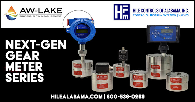
AW-Lake Process Flow Measurement introduced its Next-Generation Gear Meter Series, which features tighter tolerances, higher resolutions, higher standard pressure ratings (6000 psi), improved accuracy, wider turndowns (100:1), and a new low-viscosity series. The Next-Generation Gear Meters include high-performance materials. They have a high chemical resistance to operate safely in abrasive or filled fluids, long service life of more than 30 years in the field, +0.1 percent repeatability, and +0.5 percent standard accuracy. These positive displacement gear meters operate in bi-directional flow applications and are unaffected by changing viscosities. 

The Gear Meters provide multiple output options, including pulse, analog, and Modbus, to deliver data in required formats for PLCs, PCs, and remote displays. When combined with AW-EDGE Lake's Flow Electronics, the Next-Generation Gear Meters enable better access, understanding, and control of a process from a smartphone. Mobile and PC-based applications simplify installation, configuration, and troubleshooting. 

The following items are part of the Next-Gen Series: 

The JV-BB Positive Displacement Spur Gear Flow Meter replaces the JV-KG Line for measuring oil, fuel, polyurethane, brake fluid, Skydrol, and other non-abrasive, low-to-medium viscosity lubricating fluids. These gear meters are a good substitute for mag meters or oval gear technology because they have high accuracy and a wide turndown range. Units are ideal for chemical injection and dosing systems, fuel measurement, test stands, and hydraulic positioning systems. 

The JV-TC Positive Displacement Spur Gear Flow Meter replaces the JV-CG line for highly accurate, cost-effective metering of paints, adhesives, sealants, light, and heavy fuel oils, resins, lubricants, and petrochemical products. The JV-TC Gear Meters are ideal for metering small-particle fluids with medium to high viscosity in filling and dosing systems, as well as two- and three-component mixing systems. 

The JVH Positive Displacement Spur Gear Flow Meter measures oil, fuel, additives, and chemicals in hazardous environments. The gear meters operate in systems rated at 15,000 psi (1035 bar). Markets include offshore production platforms for chemical injection, land-based oil recovery sites, and chemical processing plants.  

The JV-UF Positive Displacement Spur Gear Flow Meter is a new series for measuring flow rates of low viscosity fluids such as kerosene, fuels, and odorants at very low flow rates as low as two cc/min. The JV-UF Gear Meters are ideal for chemical injection skids, fuel, and solvent measurement, liquid seal dispensing, batching, and dosing.

Hile Controls of Alabama
http://hilealabama.com
800.536.0269

Selection and Calibration of a Turbine Flow Meter Whitepaper

Flow Technology
Turbine flow meters have been an effective flow measurement technology for many years. Advancements in other measuring technologies in recent years have provided many options when selecting a meter for a flow measurement application. This has the benefit of allowing the user to select the measuring technology that provides the optimum characteristics for the specific application. The downside of all these measurement options is the user must have a significant understanding of many technologies in order to make the best educated decision when selecting the meter.
Flow Technology
The intent of this paper, courtesy of FTI Flow Technology, is to provide the reader with a basic understanding of the operational characteristics and calibration methods of turbine flow meters. The information provided is targeted at liquid meter applications. Turbine meters are also successfully used in gas applications. The operational characteristics of gas meters are basically the same as liquid meters, however the calibration methods and procedures are worthy of a paper specific to gas applications and will not be address at this time.


Hile Controls of Alabama
https://hilealabama.com
800.536.0269

What Are Coriolis Flow Meters?

Coriolis flow meter twisting
Animation of how the Coriolis flow meter tubes twist
in response to a flow/no-flow condition.
Coriolis mass flow meters are designed to measure almost any fluid across any application. Built on the Coriolis Principle, these meters measure the mass of the fluids directly (rather than volume) and do not require temperature or pressure compensation for accuracy.

Measuring Principle

The Coriolis measuring principle is based upon the physical effect a moving mass has on a body in a rotating frame of reference. This moving mass exerts an apparent force on the body, causing a deformation. This force is called the Coriolis force. It does not act directly on the body, but on the motion of the body. This principle is used in Coriolis flow meters.

Operation

A Coriolis flow meter consists of two parallel tubes that are made to oscillate using a magnet. These oscillations are recorded by sensors fitted at the inlet and outlet of each tube. In a no-flow state, the oscillations are synchronized, since there is no mass exerting any force on the tubes. When fluid or gas flow exists through the tubes,  Coriolis forces are generated, causing the tubes to deflect or twist in proportion to the mass flow rate of the medium.

Coriolis Flow Movement


Three Styles of Coriolis Flow Meters

U-Shaped Coriolis Flow Meters:
U-Shaped Coriolis Flow Meter

These flow meters utilize two tubes arranged in the shape of the letter ‘U’, a magnet and coil assembly, and sensors at the inlet and outlet of the tubes. Coriolis forces exerted by the flow medium are used to determine the mass flow rate and density of the medium.


Micro-bend Shaped Coriolis Flow Meters:

Micro-bend Shaped Coriolis Flow Meter
These flow meters utilize of two U-Shaped tubes in a casing with a considerably smaller radius than conventional U-Shaped Coriolis flowmeters. The smaller radius ensures a more compact instrument with significantly lower pressure differential values compared to other flow meters.


Triangle Shaped Coriolis Flow Meters:

Triangle Shaped Coriolis Flow Meter
The Triangular flow meter is the most compact style of Coriolis mass flow meters, designed specifically to provide optimum performance in low-flow applications. It utilizes a single flow tube which is considerably smaller in size than the conventional U-Shaped tube.

For more information about Coriolis flow meters, contact Hile Controls of Alabama by visiting their web site at https://hilealabama.com or by calling 800-536-0269.

Turbine Flow Meters

turbine flow meters, flowmeters, for industrial process measurement
Turbine flow meters area available in a wide range
of sizes and construction materials.
Image courtesy FTI Flow Technology, Inc.
Precision turbine flow meters are specially designed to accommodate a broad range of precise fluid measurement applications, though differing models and variants tend to be targeted at specific application conditions. They accommodate greater flow rates with lower pressure drops than other meters in their class. The turbine rotates as process fluid passes through the instrument, and special pickups placed around the perimeter of the meter sense the passage of the rotor blades. This produces a high-frequency digital output suitable for interfacing with an assortment of processing, readout and recording equipment. Some turbine flow meters have a symmetrical bi-directional design that supports reverse flow applications without a reduction in accuracy or capacity.

Operating Principle

The following paragraph is mostly excerpted from "FT Series Turbine Flow Meters", an IOM published by Flow Technology, Inc. (document ID is TM-86675, Rev AG) ...with some editing.
A turbine flow meter is a volumetric flow measuring instrument. The flow sensing element is a freely suspended, bladed rotor positioned axially in the flow stream with the flowing fluid pushing against the blades. The rotational speed of the rotor is proportional to the velocity of the fluid. Since the flow passage is fixed, the turbine rotors rotational speed is also a true representation of the volume of fluid flowing through the flow meter. The rotation of the turbine rotor generates electrical pulses in the pickoff that is attached to the flow meter housing in close proximity to the turning rotor. Each one of these pulses represents a discrete volume of fluid. The frequency or pulse repetition rate represents the volumetric flow rate and the accumulated pulse total represents the total volume measured.
Maintenance

A turbine flow meter is a mechanical device. The primary moving part is the rotor, but its balance and bearings need to be kept in good working order to avoid offset of the flow reading. Regular maintenance commonly involves withdrawing of the rotor and internal parts from the body and conducting a cleaning and inspection for corrosion or contamination of the rotor assembly by accumulation of foreign material. In some cases where foreign material buildup is inevitable, a means to isolate and flush the meter with a solvent after use can contribute greatly to reducing the overall maintenance burden.

Installation

Electrical connection and grounding requirements for turbine flow meters are similar to other process measurement instruments. Mechanical installation requires consideration of a number of factors that my impact unit performance. Delivering properly conditioned flow to the instrument inlet and removing or dampening forces and conditions which may produce velocity profile disturbances is a key element of a successful installation. Paying careful attention to flow conditioning at the outset of installation and planning will yield results for the life of the unit. Here is an example of a recommended installation profile, courtesy of FTI Flow Technology, Inc.
turbine flow meter installation drawing
Schematic representation of turbine flow meter installation.
Image courtesy FTI Flow Technology, Inc.
Summary

Turbine flow meters, with their simple, durable construction and wide operating range, are an effective and beneficial choice for a number of industrial process applications. As with all instrumentation, there are a number of factors to consider when making a selection. Share your flow measurement challenges and requirements with instrumentation specialists, combining your process knowledge with their product application expertise to develop effective solutions.

Hile Controls of Alabama Expands Product Offering

oil refinery process control
Continuing its drive to provide top flight solutions to industrial process measurement and control challenges, Hile Controls of Alabama has added several new lines of instruments and equipment to its offering.


  • Tektrol provides process measurement and control products for flow, level, temperature and pressure measurement and control valves and analyzer systems.
  • Premier Industries is a designer and manufacturer of proprietary specialty gas and hydraulic regulators, valves, and systems for a diverse range of applications and markets.
More will be coming to illustrate the quality products offered by these new lines for Hile. Detailed information is available through a quick contact with our office. Share your process measurement and control challenges, leveraging your own knowledge and experience with the product application expertise at Hile Controls of Alabama to develop the best solution.

Ultrasonic Flow Measurement Overview

clamp on ultrasonic flowmeter llow meter
Clamp-on ultrasonic flow meter does not contact
process media
Courtesy Micronics
Ultrasonic flow meters measure, via sound waves inaudible to humans, the velocity of fluid flowing through a conduit. The conduit can be a recognizable closed piping run, or open channels, flumes, or chutes. The technology is predominantly applied to liquids and gases.

There are three types of ultrasonic flow meters, differentiated by their means of measurement. An open channel flow meter derives liquid depth by computing geometrical distance, combining it with a velocity measurement and known dimensional properties of a flume or other channel. A Doppler shift flow meter reflects ultrasonic energy off sonically reflective materials and measures the frequency shift between emission and reflection to derive a fluid velocity measurement. The contrapropogating transit-time flow meter, more recognizably, the transmission flow meter. The transmission flow meter has two versions: the in-line and the clamp-on. The in-line configuration is intrusive, with flow meter hardware extending into and exposed to the measured media. A clamp-on style ultrasonic flow meter resides on the outside of the pipe, emitting and receiving the ultrasonic pulses through the pipe wall. These process measurement tools, using ultrasound technology, have the ability to measure fluid velocity and calculate volumetric, mass, and totalized flow. The use of ultrasonic flow measurement is prevalent in the oil and gas, nuclear, wastewater, pharmaceutical, and food and beverage industries. It is also employed in energy management systems as a means to measure energy demand.

For intrusive flow meters, sensors are fitted opposite one another and alternate bouncing ultrasonic signals back and forth in the pipe, in an almost tennis-like format. In an elementary explanation, by increasing the number of sensors, engineers are able to decipher flow proportions through calculations of velocity between sensory transmissions; thereby, the flow volume can be computed.

For externally mounted flow meters, a clamp-on device affixes the flow meter measurement elements to the pipe. One special characteristic of clamp-on flow meters is the ability to transmit ultrasonic signals through piping up to four meters in diameter, making them suitable for application in very large systems such as those found in hydroelectric or wastewater installations. The clamp-on arrangement also facilitates addition of a flow measurement point to an existing system without process interruption.

The technology is pervasive in the processing industries, having its particular niche of applications where it excels. Proper installation is a key element in producing reliable and consistent results. Ultrasonic energy flow technology is used for custody transfer of natural gases and petroleum liquids. Custody transfer usually entails following industry, national, and government standards and regulations. Other popular applications include compressed air system monitoring and energy usage metering.

Ultrasonic flow meters, with no moving parts, are comparatively low maintenance and self-diagnosing. Temperature and pressure measurements are needed to calculate mass flow of gases. When measuring liquid mass flow in pipes, it is generally necessary for the pipe cross section to be media filled in order to obtain reliable results.

Whatever your flow measurement challenge, share it with a process measurement specialist. Combine your process knowledge with their product application expertise to develop effective solutions.

Positive Displacement Liquid Flowmeters

positive displacement liquid flow meter for industrial process measurement
Positive displacement flowmeter
Rotating gear type
Courtesy Flow Technology
Unlike other liquid flow measurement technologies that rely on the measurement of a physical property of flowing media to produce a volumetric or mass flow measurement, a positive displacement flowmeter provides a direct indication of actual volumetric flow rate. There are a number of different positive displacement flowmeter designs in use throughout industrial, commercial, and even residential installations.

  • Oscillating piston
  • Gear
  • Nutating disk
  • Rotary vane
  • Diaphragm 

Each of the designs, and any others that would be classified as positive displacement, contain a mechanical structure through which the fluid must travel on its path from source to target. The fluid motion drives the mechanical assembly, which contains pathways of known volume. As the fluid motion drives the positive displacement flowmeter assembly, its rotational, oscillating, or other regular movement is counted, often by electronic means using magnetic pickups on moving assembly. The counts can be used to indicate current flow rate, or totalized to measure total flow volume. Additional inputs about fluid properties can be used to calculate mass flow, as well.

Positive displacement flowmeters can be applied to liquid or gaseous media, with the selection of the mechanical internals being a significant factor in the suitability of a design for a particular application.

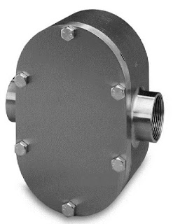
Rotating gear flowmeters are especially well suited for high viscosity liquids. As the fluid drives the gear assembly, liquid is trapped in the spaces between the gear lobes and the housing. The rotation of the gear moves the liquid from the inlet port to the outlet. The product datasheet provided below has a good illustration of the geared positive displacement flowmeter operating principle. In many cases, a positive displacement flowmeter appears similar to a positive displacement pump, with the primary difference being that the pump is provided with its own motive power (a motor) and the flowmeter is driven by the process fluid.

Share all of your flow measurement requirements and challenges with process instrumentation experts, combining your own process knowledge and experience with their product application expertise to develop effective solutions. 


Accurate Thermal Metering For Building HVAC Energy Management

energy management meter btu meter ultrasonic inline thermal energy meter
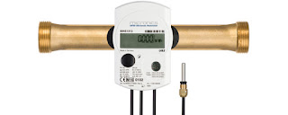
Ultrasonic In-line Thermal Energy Meter
Courtesy Micronics
The modern business climate has, for some now, been spooling up demand for accountability and, even more so, efficiency. Whether you think of efficiency as "doing more with less" or just avoiding the waste of financial, human, or natural resources the end result is the same and calls for similar prerequisites.

We live in a society of buildings, each with a mapped out function. Most buildings are predominantly occupied by people, bringing a requirement to maintain temperature, relative humidity, and air quality at levels of suitable comfort for human occupants. The energy consumption involved with providing that level of comfort stands as a bold line item in the operating expense ledger for any building. That is where accountability and efficiency come in. It is in the building stakeholders' interest to have knowledge regarding rates and quantity of thermal energy usage, as well as efficiency measures of delivered output per unit of input energy.

HVAC (Heating, Ventilation, Air Conditioning) primarily is an endeavor that generates and moves thermal energy throughout an enclosed space. Commercially available technology now allows a building operator to accurately measure that movement of thermal energy throughout a system or building. The process is generally called BTU metering and has a number of justifiable benefits.

  • Real time equipment performance measurement.
  • Sub metering can indicate specific areas of consumption.
  • Ability to directly bill multiple tenants in a single building for their thermal energy usage.
  • Monitor and balance energy flows.

BTU metering essentially involves inlet and outlet temperature measurement of heat transfer liquids, along with their flow rate. While the principle is simple, the intricacies of the measurement methods and equipment accuracy can have a substantial impact on the accuracy, and thus the benefit, of the measurement data. Additionally, adding more instrumentation to an already complex system can create an additional on-going maintenance and calibration burden to retain the necessary levels of accuracy and function. Success at gaining the benefit of the performance data while minimizing the additional maintenance burden due to the instrumentation should be the goal.

One solution calls for the use of clamp on or in-line ultrasonic flow meters to measure liquid flow, coupled with temperature measurement in a single unit that will perform necessary calculations and provide output data in useful engineering units. An overarching benefit of the clamp on meter is its non-invasive nature, allowing its retrofit to in-place systems with no disturbance to existing piping. Here are some other characteristics of a highly effective BTU measurement unit:
  • No wear mechanism as part of the flow measurement unit
  • Traceable accuracy of flow and temperature measurements
  • Simple installation in new or retrofit applications without disruption to system operation
  • Reliable and maintenance free operation
  • Accurate measurement from near zero flow rate to maximum system flow
  • Stable sensing with no zero drift
  • Communications protocol to match building energy management system
  • Large storage cache for data, in case of communication failure
  • Common output signals, 4-20 ma or other, usable with selected ancillary equipment
Selecting the right equipment or instrumentation is the most important step along the path of adding measurement capability to increase efficiency. Without a solid stream of reliable data, useful decisions become difficult. Contact a product application specialist and share your requirements and goals. Combining your process and system knowledge with their product application expertise will produce a good outcome.

Ultrasonic Gas Flow Meters for Custody Transfer and Process Control


Custody transfer of natural gas is accomplished through pipelines, with billings calculated based upon measurements of gas flow made during the transfer. The measurement instruments used in custody transfer operations must employ technology that is recognized and accepted by all the parties involved in the transaction. Additionally, the devices employed should be scrupulously maintained and of rugged design in order to provide continuous accurate operation.

Volumetric flow measurement in gas lines can be reliably accomplished using ultrasonic flow meters specifically designed and configured for the task. Ultrasonic gas flow measurement relies on the principle of transit time differential. Precise measurements are made of the time between transmission and receipt of the ultrasonic signal as it passes through the media within the pipe. The sound velocity transit time is affected by the velocity of the media, providing a means to determine media velocity and calculate the flow volume.

Adding multiple measuring paths can provide higher accuracy, measurement redundancy, or a combination of both. Integrating temperature and pressure sensors into the instrument enables provision of additional necessary data from a single point.

Proper device selection and configuration for each application will provide the best results. More information is available from product application specialists. Share your flow measurement requirements and challenges with them, combining your process knowledge with their product application expertise to produce the most effective solutions.


Turbine Flow Meters for Process Measurement and Control

Several industrial process control turbine flow meters
Turbine Flow Meters
Courtesy Flow Technology
Hile Controls of Alabama represents Flow Technology Inc., a manufacturer of turbine, magnetic, ultrasonic, and positive displacement flow meters utilized in process measurement and control. The company also manufactures flow meter calibration equipment, and they have summarized some useful information regarding turbine flow meters into a concise white paper, which is included below. The paper provides a description of how a turbine flow meter operates, and continues with a short narrative of turbine flow meter advantages for certain applications. Calibration procedures are also outlined, with a combination of technical and non-technical language that provides useful information and understanding to the expert and not so expert reader. Concepts are illustrated to provide additional clarity.

Browse the paper. The text portion is just a few pages. Share your flow measurement challenges with a product specialist and combine your process experience with their product expertise. That is where the best solutions come from.