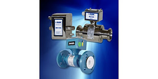
Magnetic Flow Meters: Principles and Applications

industrial flow meters
Industrial flowmeters
Image courtesy Flow Technology, Inc.
Crucial aspects of process control include the ability to accurately determine qualities and quantities of materials. In terms of appraising and working with fluids (such as liquids, steam, and gases) the flow meter is a staple tool, with the simple goal of expressing the delivery of a subject fluid in a quantified manner. Measurement of media flow velocity can be used, along with other conditions, to determine volumetric or mass flow. The magnetic flow meter, also called a magmeter, is one of several technologies used to measure fluid flow.

In general, magnetic flow meters are sturdy, reliable devices able to withstand hazardous environments while returning precise measurements to operators of a wide variety of processes. The magnetic flow meter has no moving parts. The operational principle of the device is powered by Faraday’s Law, a fundamental scientific understanding which states that a voltage will be induced across any conductor moving at a right angle through a magnetic field, with the voltage being proportional to the velocity of the conductor. The principle allows for an inherently hard-to-measure quality of a substance to be expressed via the magmeter. In a magmeter application, the meter produces the magnetic field referred to in Faraday’s Law. The conductor is the fluid. The actual measurement of a magnetic flow meter is the induced voltage corresponding to fluid velocity. This can be used to determine volumetric flow and mass flow when combined with other measurements.

The magnetic flow meter technology is not impacted by temperature, pressure, or density of the subject fluid. It is however, necessary to fill the entire cross section of the pipe in order to derive useful volumetric flow measurements. Faraday’s Law relies on conductivity, so the fluid being measured has to be electrically conductive. Many hydrocarbons are not sufficiently conductive for a flow measurement using this method, nor are gases.

Magmeters apply Faraday’s law by using two charged magnetic coils; fluid passes through the magnetic field produced by the coils. A precise measurement of the voltage generated in the fluid will be proportional to fluid velocity. The relationship between voltage and flow is theoretically a linear expression, yet some outside factors may present barriers and complications in the interaction of the instrument with the subject fluid. These complications include a higher amount of voltage in the liquid being processed, and coupling issues between the signal circuit, power source, and/or connective leads of both an inductive and capacitive nature.

In addition to salient factors such as price, accuracy, ease of use, and the size-scale of the flow meter in relation to the fluid system, there are multiple reasons why magmeters are the unit of choice for certain applications. They are resistant to corrosion, and can provide accurate measurement of dirty fluids – making them suitable for wastewater measurement. As mentioned, there are no moving parts in a magmeter, keeping maintenance to a minimum. Power requirements are also low. Instruments are available in a wide range of configurations, sizes, and construction materials to accommodate various process installation requirements.

As with all process measurement instruments, proper selection, configuration, and installation are the real keys to a successful project. Share your flow measurement challenges of all types with a process measurement specialist, combining your process knowledge with their product application expertise to develop an effective solution.


Dampers and Louvers Used in Power Plants, Refineries, Boilers, and Furnaces

pneumatic damper drives, damper positioners
Several sizes of pneumatic damper drives
Image courtesy Rosemount Analytical - Emerson
A damper (also known as a louver) is a multi-element flow control device generally used to throttle large flows of air at low pressure. Dampers find common application in furnace and boiler draft control, and in HVAC systems. Common damper designs include parallel and radial configurations of the vanes.

Parallel-vane dampers resemble a Venetian blind, with multiple parallel rectangular vanes synchronously rotated to throttle flow through a rectangular opening. The rectangular shape of the assembly facilitates installation in rectangular duct. The vanes are mechanically linked so they function as one. A manual drive can be used to set the vane position. More commonly, an automated drive positions the vanes in response to a control signal.

Radial-vane dampers use multiple vanes arranged like petals of a flower to throttle flow through a circular opening or duct. Levers and linkages on the periphery of the tube synchronize the motion of the multiple vanes so they rotate at the same angle. Mechanical linkage to an external drive point enables position control similar to that of rectangular dampers.

Automated dampers can be positioned by a number of actuation means. A common design employs a double action pneumatic cylinder, along with integrated pilot valve and controls, to position the damper vanes. A example of such a device is pictured above and detailed in the document provided below.

Used in critical applications commonly found in power plants, refineries, boilers, and furnaces, these damper and drive combinations are coupled with combustion analysis instruments to provide precise combustion gas management and increased boiler efficiency,  with lower fuel consumption, reduced emissions, and reduce maintenance cost.

Share your combustion control and large air flow control challenges with an application specialist. Leverage your own knowledge and experience with their product application expertise to develop an effective solution.

Parts of this post are reprinted from Lessons In Industrial Instrumentation by Tony R. Kuphaldt – under the terms and conditions of the Creative Commons Attribution 4.0 International Public License.


High Accuracy Low Differential Pressure Gauge


Dwyer has a new line of their well recognized Magnehelic differential pressure gauges. The new high accuracy series is intended for applications where accuracy in low pressure or differential pressure ranges is key. Six point calibration certificate, mirrored scale, wide selection of ranges, and the ability to customize the instrument are a few of the key new features. The short video tells the story.

Reach out to a process instrumentation specialist for all the details on the new models. Share your process measurement challenges with them, combining your own knowledge and experience with their product application expertise to develop an effective solution.

Manufacturer Donates Exhibit to Science Museum

equipment or control enclosure cooling units of various sizes
Advanced Cooling Technologies manufactures a range of  heat
transfer products, such as these enclosure coolers.
Image courtesy of Advanced Cooling Technologies
When a business does a good public service deed, it should be known publicly. One of the manufacturers represented by Hile Controls of Alabama, Advanced Cooling Technologies, created and donated an interactive science exhibit on heat transfer principles to the Lancaster Science Factory in Lancaster, PA.

You can read more about the exhibit and the Lancaster Science Factory in the article included below. Kudos and applause to ACT for taking the time and effort to create and contribute this exhibit that helps students learn about science.

For more information about ACT products, you can contact Hile Controls of Alabama.