Showing posts with label pressure. Show all posts

Sanitary Steam Traps and the Role They Play in Temperature Validated Steam-in-Place

Sanitary Steam Traps and the Role They Play in Temperature Validated Steam-in-Place

This video explains the role of the steam trap in successful temperature-validated SIP. Courtesy of Steriflow. Click here to watch video.

Steam trap design and operation play a fundamental role in successful temperature-validated SIP. If the steam trap does not open at the correct time and temperature to drain condensate, it can adversely affect heat-up time and whether the temperature hold is successful. It will negatively affect your revenue because of asset startup delays if it isn't.

SIP (Sterilize, or Steam In Place) is timed sterilization of the upstream and downstream biopharmaceutical production train using clean Steam. It is part of a 5 step sanitization routine that occurs after every production batch and follows the final rinse after CIP (Clean In Place). SIP ensures that every square inch of the production train that comes in contact with drug substance inputs, drug substance, or the final drug product is "sterilized" to ensure no microbiological activity in the system.

Clean Steam (made from USP Purified Water) is circulated through all of the process tubing during this stage and enters large vessels through spray balls embedded in the vessel ceiling.

SIP is a temperature-validated process, meaning that sterilization events are proven by measuring the event's temperature and recording the data. The minimum sterilization regimen requires the injection of clean Steam into all piping and vessels for at least 1/2 hour after reaching a minimum temperature of 250°F (121°C). If the temperature falls below 250°F (121°C) during the temperature hold period, a temperature validation fault gets logged, and SIP repeats.

Validation temperature sensors (usually RTD's) are placed at the condensate outlets of process equipment to ensure that the sterilization temperature meets the specific regimen designed for the process system. The sensing elements are usually designed with integral sheathes and Tri-Clamp™ connections and clamp directly to tubing tees, or the element inserts into a Tri-Clamp™ thermowell connected to the tee. The sensors usually are twelve to eighteen (12 - 18) inches (300 - 450mm) upstream of the clean steam trap where the condensate exits the piping or vessel.

Hile Controls
800-536-0269
Understanding Pressure-based Flowmeters

A “plug” of fluid can be accelerated by applying a difference of pressure across its length. The amount of pressure applied will be in direct proportion to the density of the fluid and its rate of acceleration. Conversely, we may measure a fluid’s rate of acceleration by measuring the pressure developed across a distance over which it accelerates.

We may easily force a fluid to accelerate by altering its natural flow path. The difference of pressure generated by this acceleration will indirectly indicate the rate of acceleration. Since the acceleration we see from a change in flow path is a direct function of how fast the fluid was originally moving, the acceleration (and therefore the pressure drop) indirectly indicates fluid flow rate.

A very common way to cause linear acceleration in a moving fluid is to pass the fluid through a constriction in the pipe, thereby increasing its velocity (remember that the definition of acceleration is a change in velocity). The following illustrations show several devices used to linearly accelerate moving fluids when placed in pipes, with differential pressure transmitters connected to measure the pressure drop resulting from this acceleration:

Pressure-based Flowmeters

Another way we may accelerate a fluid is to force it to turn a corner through a pipefitting called an elbow. This will generate radial acceleration, causing a pressure difference between the outside and inside of the elbow which may be measured by a differential pressure transmitter:

Pressure-based Flowmeters

The pressure tap located on the outside of the elbow’s turn registers a greater pressure than the tap located on the inside of the elbow’s turn, due to the inertial force of the fluid’s mass being “flung” to the outside of the turn as it rounds the corner.

Yet another way to cause a change in fluid velocity is to force it to decelerate by bringing a portion of it to a full stop. The pressure generated by this deceleration (called the stagnation pressure) tells us how fast it was originally flowing. A few devices working on this principle are shown here:

Pressure-based Flowmeters


Reprinted from "Lessons In Industrial Instrumentation" by Tony R. Kuphaldt – under the terms and conditions of the Creative Commons Attribution 4.0 International Public License.

Your Choice for Process Control Instrumentation - Hile Controls of Alabama


When you need pressure, temperature, level, flow, gas detection or analytical instrumentation, think Hile Controls of Alabama.  Hile provides process instrumentation for the oil and gas, chemical, power, plastics, mining, water and waste water, pharmaceutical and bio-pharmaceutical, food and beverage, pulp and paper, and government-related industries. Located in Pelham, Alabama, Hile Controls of Alabama proudly serves the states of Alabama and Mississippi, as well as Western Tennessee and the Florida Panhandle.

https://hilealabama.com
800-536-0269

Wrap Up 2017 for Hile Controls of Alabama

Process automation
The current year is closing out quickly. Here at Hile Controls of Alabama, we want to extend our thanks to all those that have supported our business and provided us with opportunities to build and improve our business and yours.

A number of product line expansions were put in place this past year.

In addition to new products, we also continued to train and learn, in order to better meet whatever challenges we face. We look forward to every opportunity to serve our customers in the new year.

Hile Controls of Alabama Expands Product Offering

oil refinery process control
Continuing its drive to provide top flight solutions to industrial process measurement and control challenges, Hile Controls of Alabama has added several new lines of instruments and equipment to its offering.


  • Tektrol provides process measurement and control products for flow, level, temperature and pressure measurement and control valves and analyzer systems.
  • Premier Industries is a designer and manufacturer of proprietary specialty gas and hydraulic regulators, valves, and systems for a diverse range of applications and markets.
More will be coming to illustrate the quality products offered by these new lines for Hile. Detailed information is available through a quick contact with our office. Share your process measurement and control challenges, leveraging your own knowledge and experience with the product application expertise at Hile Controls of Alabama to develop the best solution.

Foundation Fieldbus Equipped Instrumentation – Part One

Foundation filedbus capable pressure transmitter
Foundation fieldbus capable instruments and devices
provide benefits to process operators
Image courtesy Autrol
Autonomous control and digital instrumentation are two capabilities enabling highly precise or complex execution of process control functions. FOUNDATION fieldbus instrumentation elevates the level of control afforded to digital field instrumentation where, instead of only communicating with each other, instruments involved in particular process control systems can independently facilitate algorithms typically reserved for instruments solely dedicated to controlling other instruments. Fieldbus capable instrumentation has become the standard instrumentation for many process industry installations due to the fact the FOUNDATION design principle streamlines process systems. A large contributor to FOUNDATION’s success has been faster installation as opposed to operational controllers which do not feature the fieldbus configuration. Newer process companies, or process control professionals seeking to establish a new system, have gravitated towards fieldbus due to the combined advantages of system conciseness and ease of implementation.

In a typical digital control system, dedicated controllers communicate with field instrumentation (the HART protocol is a prime example of digital communication at work in the industry). The host system controls configuration of instruments and serves as a central hub where all relevant control decisions are made from a single dedicated controller. Typically, these networks connect controllers and field devices through coupling devices and other ‘buses’ which streamline many different instruments into a complete system.

FOUNDATION fieldbus approaches the same network scheme with an important difference. Whereas in a legacy or more conventional system, either algorithmic or manual decisions would need to be implemented via the dedicated system level controllers, instruments utilizing FOUNDATION fieldbus architecture can execute control algorithms at the local device level. The dedicated controller hub is still present, so that operators can view and monitor the entire network concurrently and make status changes. Algorithmic execution of control functions becomes entirely device reliant thanks to the FOUNDATION protocol. Additionally, even though FOUNDATION implements an advanced configuration, some operators use the capabilities introduced in the fieldbus upgrade to implement specific algorithms via each device while concurrently maintaining algorithms in the central controller. This dual algorithmic configuration allows for several advantages, including the ability for increased system precision.

Since individual devices in the control process are calibrated and able to execute their own control functions, issues in the process with particular devices can be isolated and dealt with in a more specified manner by technicians using the instruments in the field. The central operator retains the capacity to use the control hub to alter and direct the control system.

Diaphragm Seals Protect Pressure Measurement Instruments

diaphragm seal for pressure gauge or transmitter
Diaphragm Seal
Courtesy Wika
Pressure measurement is a common element of industrial operations or control systems. Fluid processing can often involve media that is potentially harmful to pressure sensing devices. The media may be corrosive to the sensor material, or other media properties may impact the performance or usable life of the instrument. In process control environments, diaphragm seals play a role in protecting items like pressure sensors from damage by process fluids. The diaphragm seal is a flexible membrane that seals across the connecting path to a sensor and isolates the sensor from the process media. System pressure crosses the barrier without inhibition, enabling accurate measurement, but the process fluid does not. Typical materials composing diaphragm seals are elastomers, with a wide variety of specific materials available to accommodate almost every application.

In the operating principle of the diaphragm seal, the sealed chamber created between the diaphragm and the instrument is filled with an appropriate fluid, allowing for the transfer of pressure from the process media to the protected sensor. The seals are attached to the process by threaded, open flange, sanitary, or other connections. Diaphragm seals are sometimes referred to as chemical seals or gauge guards. Stainless steel, Hastelloy, Monel, Inconel, and titanium are used in high pressure environments, and some materials are known to work better when paired with certain chemicals.

Sanitary processes, such as food, beverage, and pharmaceuticals, use diaphragm seals to prevent the accumulation of process fluid in pressure ports, a possible source of contamination. If such a buildup were to occur, such as milk invading and lodging in a port on a pressure gauge, the resulting contamination compromises the quality and purity of successive batches. Extremely pure process fluids, like ultra-pure water, could be contaminated by the metal surface of a process sensor. Some pneumatic systems rely on the elimination of even the smallest pressure fluctuations, and diaphragm seals prevent those by ensuring the separation of the process materials from the sensors.

Diaphragm seals are not without some application concerns, and devices are now built to address and counter many potential issues related to the use of diaphragm seals with process monitoring instruments and equipment. Products seek to eliminate any and all dead space, allow for continuous process flow, and are self-cleaning thanks to continuous flow design. Some high pressure seals come equipped with anti-clogging features, accomplished by the elimination of internal cavities while protecting gauges. Multi-purpose seals reduce temperature influence and improve instrument performance while pinpointing and diffusing areas of high stress. These pre-emptive measures result in longer instrument life-cycles and improved performance while ensuring protection from corrosion.

There are numerous options and available diaphragm seal variants. Share your application specifics with a product specialist, combining your own process knowledge and experience with their product application expertise to develop an effective solution.

Melt Pressure Measurement

section view of plastics extruder
Section view of basic plastic extruder
Wikipedia https://en.wikipedia.org/wiki/Plastics_extrusion
The manufacture of plastic parts, extrusions, and films are all similar in that they involve the melting of solid plastic, then the forming of it into some output product. In a common extrusion process, dry solid base material, plastic flakes, pellets, powder, or granules, is fed into a screw. The screw is within a tubular housing called a barrel and is driven rotationally by a motor. The machining of the screw, and its rotation, forces the plastic material into an continually decreasing volume as it moves along the length of the screw/barrel assembly. The friction and pressure induced upon the plastic, as well as some carefully controlled heating along the barrel, melt the plastic in a predictable fashion. The melted plastic is forced through a breaker plate supporting screens that serve as filters to retain particulate contaminates from the liquid plastic. The liquified plastic, called a "melt", is driven by the screw motion out the end of the machine and into a forming stage of the process.

Producing melt with the proper characteristics for the forming stage involves careful measurement and control of temperature along the barrel. Multiple PID controllers and heaters typically create several heat zones along the screw length. Monitoring the melt pressure is also an important element of process control.

One company, GP:50 Melt Pressure, manufactures temperature sensors, pressure transducers, and other measurement equipment specifically tailored for the plastics industry. The company's sharpened focus on a single industry has produced a range of specialized products that meet specific application requirements and interface well with the machinery and systems used in plastics forming. Pressure and temperature sensors and transmitters are configured with options that reflect the requirements of plastic forming operations, a reflection of the company's extensive experience in this arena.

Share your plastics forming requirement and challenges with a product specialist, combining your process knowledge with their product application expertise to develop effective solutions.
melt pressure and temperature sensors for plastic forming

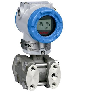
Product Overview: Autrol America Smart Transmitters for Process Measurement and Control

Smart pressure transmitter for industrial process measurement and control
Smart Pressure Transmitter
Courtesy Autrol America, Inc.
Autrol America provides pressure measurement instruments for process applications throughout every industrial segment. Pressure measurement, as an application, involves a wide range of special challenges which must be accommodated by variations in the instrument configuration and capability. Pressure measurements are used broadly for determining flow, level, and the degree of gauge or absolute pressure in a vessel or pipe. Smart transmitters provide a host of useful functions that include unit conversion, diagnostics, error detection, transfer function, signal processing, and more. Signal transmission via 4-20mA, or communication using HART for Fieldbus protocol, provides the level of connectivity needed for control systems of all types and any scale.

In the Autrol line, you will find and extensive variety of configurations and variants to meet the specific needs of almost every application.

  • Absolute pressure transmitter
  • Gauge pressure transmitter
  • Differential pressure transmitter
  • Coplanar pressure transmitter
  • High pressure transmitter
  • Direct flanged pressure transmitter
  • Remote mount pressure transmitter with diaphragm seal
  • Nuclear products pressure transmitter
  • Flow transmitter with rate and totalizing functions
A product overview flyer is included below. Share your process measurement requirements and challenges with an application expert, combining your process knowledge with their product application expertise to develop effective solutions.


Direct Drive Pressure Gauges for the Most Demanding Applications

Direct drive industrial process pressure gauge
Series 34 Direct Drive Pressure Gauge
Courtesy 3D Instruments
Pressure indication, at the location, real time. That is what a dial pressure gauge provides a process operator. Pressure gauges do not require any type of operating power, making them immune to power failures. The Bourdon tube mechanical operator is generally rugged and reliable. They are, however, subject to wear in the linkage that connects the Bourdon tube to the indicator needle over time. Extremes of vibration will also likely impact the longevity of the linkage, leading to premature failure.

3D Instruments, a manufacturer of pressure gauges and related products for industrial, commercial, and scientific applications, has developed a direct drive pressure gauge intended for use in the most rugged and demanding applications. The direct drive pressure gauges have only one working part, a helically-wound Bourdon tube made of Inconel® X-750, a flexible material that prevents the coil from losing its shape and ensures accuracy. The indicating needle is directly connected to the Bourdon tube, eliminating linkage parts. This innovation, while maintaining the benefits of some of the oldest pressure measurement technology, adds improvements in overpressure protection, burst protection, wear resistance, and life cycle cost.

A short video, included below, highlights and illustrates how the direct drive system works. Reach out to a process measurement product specialist for more detail, or solutions to any of your measurement and control challenges.

New Hydraulic Pressure Control for Wellhead Control, Hydraulic Power Units, and More

hydraulic pressure control valve
Model GHR
Hydraulic Pressure Control Regulator
Courtesy GO Regulator
Circor Energy's GO Regulator, has added a new product to its broad line of pressure regulating products. The Model GHR is a hydraulic pressure control valve targeted at applications that include wellhead control, blowout preventers, hydraulic power units, subsea actuator supply, testing applications, ballast control, and more.

The new GHR Series provides a compact, durable, and highly accurate regulator for hydraulic systems. The control knob provides a low torque, ergonomic way to set the control pressure. Standard body material is 316 SS and the unit is available in 3 port variants and multiple mounting options.

I have included a data sheet for the GHR series below which provides additional detail and some cutaway illustrations of the regulator. Share your pressure regulation applications and challenges with product application specialists. They can assist in product selection, proper sizing, and configuration to meet specific application requirements.


Video Shows How Pressure Gauges Are Made

Mechanical pressure gauges employing Bourdon tubes are common items throughout industrial process control operations. They provide accurate and immediate indication of the pressure at their connection point, without the need for external power. It can be useful to see and understand how instruments are built and upon what principles they operate. The video included below shows the process.

Bourdon tube gauges rely on the principle that a flattened and bent tube will straighten and regain its circular cross section, to some predictable and repeatable degree, in response to an increase in the pressure of a fluid inside the tube. You can see it happen in the video. The balance of the gauge is a case, a face, and mechanical linkage to transfer the Bourdon tube motion into rotation of the indicator needle on the instrument face.

Watch the video. It's informative and well done. Wika, a globally recognized manufacturer of temperature, pressure, and level measurement instrumentation, produced the video at their manufacturing facility. Share your process instrumentation challenges and requirements with an application specialist and get the best solutions.