Standalone Process Temperature Controllers

process controller with PLC functions
Sophisticated process controller features
multiple inputs and control loops, plus
PLC logic functions
Courtesy Eurotherm 
The regulation of temperature is a common operation throughout many facets of modern life. Environmental control in commercial, industrial, and institutional buildings, even residential spaces, uses the regulation of temperature as the primary measure of successful operation. There are also countless applications for the control of temperature found throughout manufacturing, processing, and research. Everywhere that temperature needs to be regulated, a device or method is needed that will control the delivery of a heating or cooling means.

For industrial process applications, the temperature control function is found in two basic forms. It can reside as an operational feature within a programmable logic controller or other centralized process control device or system. Another form is a standalone process temperature controller, with self-contained input, output, processing, and user interface. Depending upon the needs of the application, one may have an advantage over the other. The evolution of both forms, integrated and standalone, has resulted in each offering consistently greater levels of functionality.

There are two basic means of temperature control, regardless of the actual device used. Open loop control delivers a predetermined amount of output action without regard to the process condition. Its simplicity makes open loop control economical. Best applications for this type of control action are processes that are well understood and that can tolerate a potentially wide variation in temperature. A change in the process condition will not be detected, or responded to, by open loop control. The second temperature control method, and the one most employed for industrial process control, is closed loop.

Closed loop control relies on an input that represents the process condition, an algorithm or internal mechanical means to produce an output action related to the process condition, and some type of output device that delivers the output action. Closed loop controllers require less process knowledge on the part of the operator than open loop to regulate temperature. The controllers rely on the internal processing and comparison of input (process temperature) to a setpoint value. The difference between the two is the deviation or error.  Generally, a greater error will produce a greater change in the output of the controller, delivering more heating or cooling to the process and driving the process temperature toward the setpoint.

The current product offering for standalone closed loop temperature controllers ranges from very simple on/off regulators to highly developed products with multiple inputs and outputs, as well as many auxiliary functions and communications. The range of product features almost assures a unit is available for every application. Evaluating the staggering range of products available and producing a good match between process requirements and product capabilities can be facilitated by reaching out to a process control products specialist. Combine your own process knowledge and experience with their product application expertise to develop effective solution options.
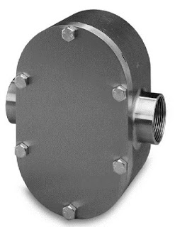
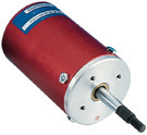
Positive Displacement Liquid Flowmeters

positive displacement liquid flow meter for industrial process measurement
Positive displacement flowmeter
Rotating gear type
Courtesy Flow Technology
Unlike other liquid flow measurement technologies that rely on the measurement of a physical property of flowing media to produce a volumetric or mass flow measurement, a positive displacement flowmeter provides a direct indication of actual volumetric flow rate. There are a number of different positive displacement flowmeter designs in use throughout industrial, commercial, and even residential installations.

  • Oscillating piston
  • Gear
  • Nutating disk
  • Rotary vane
  • Diaphragm 

Each of the designs, and any others that would be classified as positive displacement, contain a mechanical structure through which the fluid must travel on its path from source to target. The fluid motion drives the mechanical assembly, which contains pathways of known volume. As the fluid motion drives the positive displacement flowmeter assembly, its rotational, oscillating, or other regular movement is counted, often by electronic means using magnetic pickups on moving assembly. The counts can be used to indicate current flow rate, or totalized to measure total flow volume. Additional inputs about fluid properties can be used to calculate mass flow, as well.

Positive displacement flowmeters can be applied to liquid or gaseous media, with the selection of the mechanical internals being a significant factor in the suitability of a design for a particular application.

Rotating gear flowmeters are especially well suited for high viscosity liquids. As the fluid drives the gear assembly, liquid is trapped in the spaces between the gear lobes and the housing. The rotation of the gear moves the liquid from the inlet port to the outlet. The product datasheet provided below has a good illustration of the geared positive displacement flowmeter operating principle. In many cases, a positive displacement flowmeter appears similar to a positive displacement pump, with the primary difference being that the pump is provided with its own motive power (a motor) and the flowmeter is driven by the process fluid.

Share all of your flow measurement requirements and challenges with process instrumentation experts, combining your own process knowledge and experience with their product application expertise to develop effective solutions. 


Rolling Diaphragm Air Cylinders Provide Linear Motion

rolling diaphragm air cylinder for linear motion from air pressure
Diaphragm Air Cylinder
Courtesy ControlAir, Inc.
Linear motion is a mainstay of automation. A variety of methods, product designs, and power sources are employed in delivering linear motion in response to a control signal. A commonly used methodology is the pneumatically driven piston.

Air cylinders convert air pressure into linear motion using a piston sealed to the inner walls of the cylinder. The introduction of sufficient air pressure into the cylinder forces the piston to move, driving a shaft that is connected to process equipment or devices. A single acting air cylinder is provided with a mechanical means of delivering an opposing force to the motion caused by increasing air pressure. Often a spring, this mechanical force will move the piston in the direction opposite that of increasing air pressure. As the air pressure is reduced, the piston will move toward its normal, or default, position.

A double acting air cylinder enables the introduction of air pressure on either side of the piston, providing air powered movement in both directions. In this design, a loss of air pressure will result in the load driving the piston to a default position, but also provides some flexibility in operation not inherent in the spring return single action design.

The method used to create a seal between the piston and the cylinder wall impacts the operation and longevity of an air cylinder. A seal affixed to the piston that will slide along the cylinder wall as the piston is driven to each new position encumbers operation with friction and stiction. Friction will cause wear on the seal material, with its deterioration eventually impacting response of the cylinder to a control signal. Stiction, also called "static friction" or "stationary friction" refers to the resistance to relative motion of two bodies in contact with one another. In practice, we see stiction as the reason why it often takes more force to get the piston moving than it does to keep it in motion. This also causes inaccuracy in linear positioning of the load.

ControlAir overcomes both drawbacks with their Rolling Diaphragm Air Cylinders. Instead of a fixed seal between the piston and cylinder wall, a flexible diaphragm connects to the leading edge of the piston and the end of the cylinder. The piston diameter is sufficiently less than that of the cylinder, providing space for the diaphragm to roll up as the piston changes position. The design delivers negligible levels of resistance to piston movement, with resulting superior positioning capabilities.

The datasheet provided below has more detail and cutaway illustrations of both single and double acting versions, so you can see how the diaphragm concept functions. Share your linear motion and automation challenges with process control experts, combining your own experience and knowledge with their expertise to develop the most effective solutions.


Sanitary Steam Trap for Tank Heating Applications

sanitary steam trap with bypass
Mark 934 Sanitary Steam Trap
Courtesy Steriflow
Saving space, reducing parts count, minimizing potential leak points, delivering good performance under all anticipated conditions, and cost savings are all hallmarks of a successful product adaptation. The Mark 934 Sanitary Steam Trap from Steriflow accomplishes all of these things for tank heating operations in food, beverage, or biopharma settings.

The innovative steam trap is essentially two different sized traps built into a single unit. One path employs a large orifice to accommodate large flows during process heat-up, replacing the more traditional bypass line with its additional piping, fittings, and specialties. A smaller orifice handles flow required for maintenance of tank temperature. The activation of either path is automatically controlled in response to the load on the unit.

The video below provides a more in depth explanation, description, and illustration of how the Mark 934 Sanitary Steam Trap functions.

Share your steam system requirements and challenges with product application specialists, combining your own process and facilities knowledge with their product application expertise to develop effective solutions.