Showing posts with label transmitter. Show all posts

Kayden Instruments CLASSIC™ Series Thermal Dispersion Flow, Level, Interface & Temperature Switches & Transmitters

Kayden Instruments

Kayden Instruments is a leading manufacturer of flow, level, interface & temperature products in the process control community.


Their products assist organizations in the global oil and gas, pipeline, power, mining, chemical, transportation, water and wastewater, food, manufacturing, pharmaceutical, plastics, pulp & paper, and semiconductor industries to improve process efficiency.


Features that make their CLASSIC™ 800 standout amongst the competition:


Patented Design

  • Kayden’s patented designs provide the ultimate performance and features package for flow, level, interface, and temperature sensing.
  • Kayden’s products combine precision welded, highly accurate sensors, extremely rugged enclosures, and advanced digital electronics.
  • The CLASSIC 800 Series combines the failure resistance inherent in Thermal Dispersion technology with the performance and features usually reserved for much more expensive instruments.


Universal Power Input

  • Some manufacturers require upfront specifying of all options, such as relay-energized mode, at the time of order. Still, with the Kayden CLASSIC 800 series, you can select your choice of operation modes by simply pushing a few buttons.
  • The universal power input capability of the Kayden CLASSIC 800 series provides flexibility for use in all power input situations.


Discrete & Analog Outputs

  • Modbus registers via RS-485 4-20 mA analog representation of Thermal Signal.
  • Two SPDT sealed relay contacts rated @ 4 amps resistive 230 VAC or 24 VDC maximum.


Adjustments

  • Adjustable Set Point Deadbands
  • 4 Adjustable Independent Switch Point Timers


Advanced Diagnostics

  • Kayden’s CLASSIC 800 series uses an advanced microprocessor to perform continuous self-test diagnostics on the electronics and the sensor elements.
  • Any open or shorted connection will result in a FAULT indication that deactivates all relays and disables the heater circuitry.
  • An internal watchdog circuit ensures that the microprocessor code is performing as expected, and a secondary external watchdog circuit confirms the microprocessor itself is functioning. Both circuits force the contacts open, illuminate the Fault LED, and force the heater off in a malfunction, preventing the possibility of a “run-away” heater or a high thermal offset.


Intelligent User Controls

  • The Kayden CLASSIC 800 series Display Panel features very bright LED indicators for easy viewing even in direct sunlight.
  • An adjustable power-on Start-up Bypass Timer is accessible from the Display Panel for low-flow alarm pump protection applications. This feature makes it possible to disable a pump on low flow and have it automatically restart after a predetermined time in the event of a power interruption.
  • Four adjustable delay timers introduce repeatable time delay into the (setpoint) relay trip function. For example, in a pump protection application, this function will shut down the pump after the switch sensor has gone “dry” for the pre-set time (delay) limit.
  • The Kayden RCM (Remote Communications and Monitoring) Software allows all the settings to be configured remotely and saved as a file, transmitted as an email attachment, and printed for future reference.
  • The Kayden RCM Software includes the option of locking the CLASSIC 800 Series Display Panel to eliminate field adjustments or tampering.
  • Modbus allows multiple Kayden units to be connected to the same communications bus (via RS-485) and monitored simultaneously.


For more information about Kayden in Alabama, Mississippi, Western Tennessee, and Florida, contact Hile Controls of Alabama. Call them at 800-536-0269 or visit their website at https://hilealabama.com.

Communicate With HART Devices Using a Smart Phone

Bluetooth modem for Smart device communication with HART transmitters
The HM-BLE modem enables smart device communications
between HART devices and a smart phone.
Image courtesy ProComSol, Ltd
The HART communications software from ProComSol is based on the SDC-625 software from the HART Communication Foundation. Since its release in 2007, the software has developed into a full featured, stable, and reliable platform through the open source development process. Years of in-field use and user feedback are incorporated into the current version that provides full configuration saving and download. The ease of use and functionality of the package delivers benefits to any facility utilizing HART enabled devices.

A recent release now adds an iOS version of the product to the ProComSol offering, the first iOS based Smart Device Communicator Application for HART instruments. The new version brings the features and functionality of the popular DevCom android app to iPhone users.
  • Uses the registered DD files from the FieldComm Group
  • Complete access to all features of the device DD including Methods
  • Monitor PV, Multi-variables, and Device Status
  • View and edit device Variables
  • The most cost-effective DD based handheld HART communication solution available
More information is included below. A wireless modem, the HM-BLE, enables simple connection between smart phone and HART transmitter. Share your process measurement and control challenges with product application specialists, leveraging your own knowledge and experience with their expertise to develop effective solutions.


Combination Magnetic Level Gauge and Liquid Level Transmitter

combination magnetic liquid level gauge and guided wave radar transmitter
This combination of guided wave radar level transmitter
and magnetic level gauge can be further customized
to suit almost any process application.
Image courtesy ABB K-Tek
Process operations involving liquids contained in tanks and vessels invariably need instruments that provide information about the degree to which the tank is full....how much process liquid is in the tank. It is common to have a need for multiple signals or indicators, utilized in the process monitoring and control scheme for differing purposes. A continuous liquid level signal from a transmitter provides remote indication of remaining tank capacity or a measure of tank contents. Liquid level switches can be wired directly into other control circuits for safety or operational control of other machinery supplying or draining the tank. Local operators can benefit from a visual indication of tank liquid level to verify process step progress. Obtaining all this process related information from the tank can require numerous separate tank connections, fittings and space for service and maintenance access. A good solution is available.

K-Tek, an ABB brand, combines a guided wave radar transmitter and a magnetic level indicator into a single compact instrument with one set of tank connections. The instrument can be custom configured in a number of ways, with accessories that can be added to suit any application. Service valves, additional transmitters, level switches and more can be added to the instrument at the time of ordering to minimize first cost, installation time, potential leak points, fittings, piping, space requirements and more. The datasheet included below provides more detail on the available configuration options, but you should share your level measurement and control challenges with application experts for a knowledgeable recommendation. Combine your own process knowledge and experience with their product application expertise to develop an effective solution.


Comparison of 900 MHz vs 2.4 GHz for Industrial Wireless Connectivity

depiction of wireless process signal transmission in industrial setting
IOSelect provides equipment to establish wireless
process signal connections.
Image courtesy IOSelect
Wireless transmission of measurement and control signals are the future, and present, of process control. WiFi is already prevalent in higher density environments and providing benefits of reduced cabling and more. Wireless communications also can be used to connect devices over substantial distances, even globally. This article will focus on applications of moderate to long distance that will employ point to point communications of dedicated devices.

In establishing a wireless process signal connection between two points, an initial consideration will be whether to employ 900 MHz or 2.4 GHz as the radio band. There are some general implications associated with the selection.
  • Signal attenuation over any distance is greater for 2.4 GHz than 900 MHz. This generally means that 900 MHz can cover a greater distance and provide a signal of sufficient strength to properly communicate.
  • Atmospheric attenuation for either frequency band is about the same, with a very slight advantage to 900 MHz.
  • Both frequencies require "line-of-sight" to provide predictable and reliable operation. Obstructions within that zone can degrade the signal. Any obstructions with dimensions approximating the wavelength of the signal tend to have a greater impact. The wavelength of a 2.4 GHz signal is 12.5 cm (4.52 inches), 900 MHz is 33.3 cm (84.6 inches). 2.4 GHz signals are susceptible to interference by smaller objects in the transmission path than are 900 MHz signals.
  • Without getting too technical, the height of a 900 MHz antenna will need more elevation than that of a 2.4 GHz antenna in order to provide what is known as "free space propagation". This is related to the Fresnel Zone and has greater impact as transmission distance increases.
  • FCC rules allow larger transmit power ratings for 2.4 GHz radio signals than 900 MHz, increasing the potential range for 2.4 GHz.
Having a general understanding of the factors that vary between 900 MHz and 2.4 GHz and how they might impact your installation can lead to a better project outcome. Evaluate your potential installations with the above points in mind. Their impact on any particular application can vary depending upon the distance, topography, and potential obstructions. Share your wireless communications challenges with application specialists. Combining your site and process knowledge with their product application expertise will produce an effective solution.


Wireless Transmission of Industrial Process Control Signals - Practical Considerations

industrial wireless transmitter or receiver for process measurement and control
Establishing wireless process signal connections
requires consideration of a different set of factors
than a wired installation.
Image courtesy IOSelect
Establishing wireless connections for the transmission of process measurement signals is generally a straight forward task. There are, however, a vastly different set of considerations than those for a wired transmission of the same signal. In order to select the right equipment for the job, some general comprehension of radio signals can be useful.

Radio wave frequencies are below the infrared range on the electromagnetic spectrum, thus their wavelengths are comparatively long. Three things can happen to electromagnetic radiation (radio waves) when encountering a barrier.
  • Reflectance: The wave bounces off the barrier.
  • Transmittance: The wave passes through the barrier.
  • Absorbance: The wave is stopped.
Which of the three possibilities will occur depends upon a number of factors relating to the signal and the barrier, some of which include:
  • The wavelength of the radiation
  • The intensity of the radiation hitting the barrier
  • The chemical composition of the barrier
  • The physical microstructure of the barrier
  • The thickness of the barrier
Here is a conglomeration of knowledge items pulled together from a number of public sources that can be applied when considering a wireless installation.

Milliwatts (mW) are the common measurement unit of radio frequency (RF) power. A logarithmic scale of decibels, referencing 1 mW as the zero point, provides a useful way to express the comparative strength of RF signals. Using decibels, a signal strength of 1 mW is registered as 0 dBm. RF power attenuates according to a logarithmic function, so the dBm method of expressing RF power enjoys widespread use.

Industrial wireless communications applications in North America predominantly operate in either the 2.4 GHz or 900 MHz frequency range. Higher frequency will provide more bandwidth, but at the cost of reduced transmission distance and obstacle penetration. Lower frequency can require a larger antenna to attain the same signal gain.

Transmission power is not the only solution for delivering a signal. Low power signals can be successfully received by sensitive radio equipment. Reducing the data transmission rate can increase the functional sensitivity of the receiving equipment, too.

Be mindful of the existence or potential for RF background noise in your communications environment. A higher level of background noise can hamper the effectiveness of your equipment. The "noise floor" varies throughout the frequency spectrum and is generally below the sensitivity level of most equipment. Industrial environments can sometimes provide unusual conditions which may warrant a site survey to determine the actual noise floor throughout the communications area.

Radio transmission is susceptible to environmental elements on a variable basis. Since the environment can change without notice, it is useful to know the fade margin of a wireless installation. Fade margin expresses the difference between the current signal strength and the level at which the installation no longer provides adequate performance. One recommendation is to configure the installation to provide a minimum of 10dB of fade margin in good weather conditions. This level can provide sufficient excess signal strength to overcome the diminishing effects of most weather, solar, and interference conditions.

There are a number of simple methods to determine whether an installation has at least a 10 dB fade margin. Temporarily installing a 10dB attenuator on the system antenna, or installing a length of antenna cable that yields 10dB of attenuation will allow you to determine if the installation can accommodate 10dB of environmental impact on the signal. If the system operates suitably with the attenuation installed, you have at least that much fade margin.

RF signals attenuate with the square of the distance traveled, so if transmission distance is to be doubled, then the signal power must increase fourfold.

True “line of sight” signal paths are found in a limited number of installations. The number, type, and location of obstacles in the signal path can have a significant impact on the signal and contribute to what is referred to as path loss. Probably the simplest way to reduce the impact of obstacles is to elevate the antennas above them. Obstacles, in almost every case, are affixed to the earth, so their interference is reduced by elevating antennas to “see” over the obstacles.

When the signal path extends through an outdoor area, weather conditions have an impact on the path loss, with higher moisture levels increasing the loss. Large plants, most notably heavily wooded areas, can impose substantial reduction on RF signals and may require elevating antennas above the trees or using repeaters to route the signal around a forested area.

Industrial installations routinely present many reflective obstacles in the signal path. The transmitted signal may reflect off several obstacles and still reach the receiving antenna. The received signal strength will be the vector sum of all the paths reaching the antenna. The phase of each signal reaching the antenna can impact the total signal strength in a positive or negative way. Sometimes relocating the antenna by even a small amount can significantly change the strength of the received signal.

Antenna cable contributes to signal attenuation. Use high quality cable of the shortest length possible to minimize the impact on performance.

Share your connectivity challenges with application specialists, leveraging your own knowledge and experience with their product application expertise to develop an effective solution.

Hile Controls of Alabama Expands Product Offering With HART Communicator


Hile Controls of Alabama has complemented and expanded its process measurement and control offering with the ProComSol line of HART communications software.

The HART communications software from ProComSol is based on the SDC-625 software from the HART Communication Foundation. Since its release in 2007, the software has developed into a full featured, stable, and reliable platform through the open source development process. Years of in-field use and user feedback are incorporated into the current version that provides full configuration saving and download. The video provides an overview of the ease of use and functionality of the package for any facility utilizing HART enabled devices.

More information is available from process control experts. Share your process measurement and control challenges. Combine your own knowledge and experience with the product application expertise of a specialist to develop effective solutions.

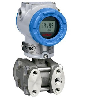
Product Overview: Autrol America Smart Transmitters for Process Measurement and Control

Smart pressure transmitter for industrial process measurement and control
Smart Pressure Transmitter
Courtesy Autrol America, Inc.
Autrol America provides pressure measurement instruments for process applications throughout every industrial segment. Pressure measurement, as an application, involves a wide range of special challenges which must be accommodated by variations in the instrument configuration and capability. Pressure measurements are used broadly for determining flow, level, and the degree of gauge or absolute pressure in a vessel or pipe. Smart transmitters provide a host of useful functions that include unit conversion, diagnostics, error detection, transfer function, signal processing, and more. Signal transmission via 4-20mA, or communication using HART for Fieldbus protocol, provides the level of connectivity needed for control systems of all types and any scale.

In the Autrol line, you will find and extensive variety of configurations and variants to meet the specific needs of almost every application.

  • Absolute pressure transmitter
  • Gauge pressure transmitter
  • Differential pressure transmitter
  • Coplanar pressure transmitter
  • High pressure transmitter
  • Direct flanged pressure transmitter
  • Remote mount pressure transmitter with diaphragm seal
  • Nuclear products pressure transmitter
  • Flow transmitter with rate and totalizing functions
A product overview flyer is included below. Share your process measurement requirements and challenges with an application expert, combining your process knowledge with their product application expertise to develop effective solutions.


Combine Two Liquid Level Technologies Into One Instrument

Combination guided wave radar transmitter and magnetic level gauge
Combination Guided Wave Radar Transmitter
and Magnetic Liquid Level Indicator
Tanks and vessels containing process liquids benefit from having two independent indications of liquid level. A local indicator with high visibility provides on-site personnel the information needed to confirm a tank fill level or coordinate other tasks. An electronic signal provides continuous liquid level information to process control operations and monitoring equipment.

K-Tek, a subsidiary of ABB, combines a guided wave radar transmitter and a magnetic level indicator into a single compact instrument, fulfilling the total requirement with one instrument, one set of tank connections.

The instrument can be configured in a number of ways, with accessories that can be added to suit any application. Details are provided by the data sheet included below.

Share your level measurement and control challenges with application experts, combining your process knowledge with their product application expertise to develop effective solutions at your facility.